SOLAR BOOST™ 2512i(X)-HV 20/25AMP 12VDC MAXIMUM POWER POINT TRACKING PHOTOVOLTAIC CHARGE CONTROLLER INSTALLATION AND OPERATION MANUAL THIS MANUAL INCLUDES IMPORTANT SAFETY INSTRUCTIONS FOR MODELS SB2512i-HV and SB2512iX-HV, SAVE THESE INSTRUCTIONS. THIS MANUAL DOES NOT APPLY TO EARLIER MODELS SB2512i OR SB2512iX COVERED UNDER ONE OR MORE OF THE FOLLOWING US PATENTS 6,111,391 • 6,204,645 © Blue Sky Energy, Inc.
Blue Sky Energy - Solar Boost 2512i-HV and 2512iX-HV TABLE OF CONTENTS IMPORTANT SAFETY INSTRUCTIONS ................................................................................................................................ 2 PRODUCT DESCRIPTION...................................................................................................................................................... 3 Features Omitted in the Solar Boost 2512i-HV ..............................................................
Installation and Operation Manual IMPORTANT SAFETY INSTRUCTIONS This manual contains important instructions for Models SB2512i-HV and SB2512iX-HV SAVE THESE INSTRUCTIONS 1. Refer installation and servicing to qualified service personnel. High voltage is present inside unit. Incorrect installation or use may result in risk of electric shock or fire. No user serviceable parts in this unit. 2.
Blue Sky Energy - Solar Boost 2512i-HV and 2512iX-HV PRODUCT DESCRIPTION Solar Boost™ 2512i-HV and 2512iX-HV are improved versions of the original SB2512i and SB2512iX 12 volt 25 amp Maximum Power Point Tracking (MPPT) photovoltaic (PV) battery charge controllers. The new HV versions retain their original 25 amp 340 watt rating when used with conventional 12 volt 36 cell PV modules, but are also able to operate up to 270 watts of higher voltage 60 cell “grid tie” type modules.
Installation and Operation Manual 3-STAGE CHARGE CONTROL The 2512 is factory configured for a 3-stage charging process, Bulk, Absorption and Float. The 3-stage charge process provides a somewhat higher charge voltage to charge the battery quickly and safely. Once the battery is fully charged a somewhat lower voltage is applied to maintain the battery in a fully charged state without excessive water loss. 3-stage charge improves battery performance and life while minimizing battery maintenance.
Blue Sky Energy - Solar Boost 2512i-HV and 2512iX-HV CURRENT LIMIT If PV input power is high enough to produce more than 25 amps of output current with 36 cell PV modules, or 20 amps with 60 cell PV modules, the 2512 will automatically limit output current to this maximum rating. Note that when the 2512 exits current limit, it will briefly show Absorption on the Charge Status Indicator even though battery voltage may be low.
Installation and Operation Manual ¾ CAUTION: The 2512 is protected against reverse battery and PV polarity, and swapped PV and battery connections, but will be damaged by reverse battery to the PV terminals. Transient voltage lightning protection is provided, but steady state voltage in excess of 50VDC on the battery or PV terminals will damage the unit. Damage of either type voids the limited warranty. ELECTROSTATIC HANDLING PRECAUTIONS All electronic circuits may be damaged by static electricity.
Blue Sky Energy - Solar Boost 2512i-HV and 2512iX-HV BATTERY AND PV WIRING A desirable installation will produce a total system wiring voltage drop of 3% or less. The lengths shown in Table 2 are one way from the PV modules to the battery with the 2512 located along the path. Length can be increased inversely proportional to actual PV IMP such that if current was reduced by 1/2 wire lengths could be doubled and still provide the same 3% voltage drop.
Installation and Operation Manual AUXILIARY BATTERY CHARGE – DIP #3 OFF The auxiliary charge function is used to charge an auxiliary battery of the same voltage as the primary battery. If the primary battery is charging in Absorption or Float, up to 2 amps is diverted to the auxiliary battery at the same charge voltage. Auxiliary battery charge is disabled during Bulk or Equalization. Use 14 awg wire to minimize voltage drop and 25 amp maximum over current protection.
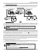
Blue Sky Energy - Solar Boost 2512i-HV and 2512iX-HV IPN NETWORK WIRING FIGURE 5 IPN Network Address – DIP’s #1, #2 & Jumper A2 ) ¾ A single controller must be set to IPN network address 0 (zero). In a multi-controller system one controller must be set to address 0 (zero) to serve as the master. The other controllers must be set to address 1-7 with no two controllers set the same. The 2512 requires that a jumper be soldered across location A2 to select addresses 4 through 7.
Installation and Operation Manual TROUBLESHOOTING GUIDE SYMPTOM Completely dead, optional display blank Unit will not switch to a Charge ON (charge status indicator OFF), Remote display if attached turns ON. Charge status indicator ON.
Blue Sky Energy - Solar Boost 2512i-HV and 2512iX-HV SYMPTOM Networked units do not seem to coordinate action or slaves do not turn on Temperature related functions do not work. PROBABLE CAUSE IPN network address set wrong ITEMS TO EXAMINE OR CORRECT One unit of a multi-unit network must be set to IPN network address 0 (zero), AND all other units must be set to different addresses 1 – 7. Network wiring problem Confirm wiring correctly in place.