
Installation Guide


Blue Sky Energy - Solar Boost 2512i-HV and 2512iX-HV
9
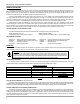
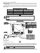
IPN NETWORK WIRING
FIGURE 5
IPN Network Address – DIP’s #1, #2 & Jumper A2
¾ A single controller must be set to IPN network address 0 (zero). In a multi-controller system one controller must be set to
address 0 (zero) to serve as the master. The other controllers must be set to address 1-7 with no two controllers set the same.
The 2512 requires that a jumper be soldered across location A2 to select addresses 4 through 7.
IPN NETWORK ADDRESS
DIP
SWITCH
MASTER SLAVES
0 1 2 3 4 5 6 7
JUMPER (A2) NO NO NO NO YES YES YES YES
# 1 (A1) OFF OFF ON ON OFF OFF ON ON
# 2 (A0) OFF ON OFF ON OFF ON OFF ON
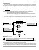
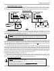
MOUNTING
¾ CAUTION: Mount the 2512 vertically to promote air flow and do not enclose in a confined space. The 2512 is not watertight and
must be protected from rain, snow and excessive moisture. The 2512 may also be installed in a standard 4
11
/
16
” square galvanized
electrical box. An optional black powder coated deluxe metal mounting box is also available. If a metal box is used DO NOT remove
or install into mounting box with power applied as damage resulting from shorting to the mounting box will void the limited warranty.
DETAILED DIMENSIONAL DRAWING
FIGURE 6
)