
Installation Guide


Blue Sky Energy - Solar Boost 2512i-HV and 2512iX-HV
5
CURRENT LIMIT
If PV input power is high enough to produce more than 25 amps of output current with 36 cell PV modules, or 20 amps with 60 cell PV modules, the
2512 will automatically limit output current to this maximum rating. Note that when the 2512 exits current limit, it will briefly show Absorption on the Charge
Status Indicator even though battery voltage may be low. If changing from 60 cell to 36 cell modules reboot the 2512 to restore 25A current limit.
OPTIONAL TEMPERATURE COMPENSATION (Omitted on SB2512i-HV)
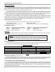
The charge voltage required by batteries changes with battery temperature. Temperature compensation of charge voltage enhances battery
performance and life, and decreases maintenance. Automatic temperature compensation can be provided using the optional battery temperature sensor
(BSE p/n 930-0022-20). The default compensation factor of –30.0mV/°C (–5.00mV/°C/cell) is appropriate for most lead-acid batteries.
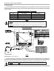
FACTORY DEFAULT CHARGE VOLTAGE SETPOINT -VS.- BATTERY TEMPERATURE
FIGURE 2
MAXIMUM SETPOINT VOLTAGE LIMIT
Maximum voltage setpoint limit places a ceiling or upper limit on the maximum charge voltage. Regardless of setpoint values entered by the user or
result from temperature compensation the 2512 will not apply a charge voltage setpoint greater than the maximum voltage setpoint limit factory configured to
15.5V. Note that actual battery voltage may briefly exceed this value by 0.1 – 0.2V as the voltage control system responds to changes in load.
MAXIMUM POWER POINT TRACKING (MPPT)
The 2512’s patented MPPT technology can increase charge current up to 30% or more compared to PWM controllers operating 36 cell PV modules.
Principal operating conditions affecting current boost performance are PV cell temperature and battery voltage, with lower PV temperature and lower battery
voltage producing greater charge current increase. In cool comfortable temperatures most systems see about 10 – 20% increase. Increase may go to zero in hot
temperatures, whereas charge current increase may easily exceed 30% with a discharged battery and freezing temperatures. MPPT also allows efficient use of
higher voltage 60 cell modules by converting their much higher voltage down to battery voltage. Ignoring conversion losses the conversion process produces an
output current roughly equal to PV current times the ratio of PV voltage to battery voltage. If a 60 cell module is operating at 23V at 5 amps and battery voltage was
14V, output charge current would be about 5 amps times 23V ÷ 14V or about 8 amps. For a more complete MPPT description see
www.blueskyenergyinc.com.
PANEL TEMPERATURE AND OUTPUT POWER
Internal power control devices use the front panel as a heatsink. It is normal for the front panel to become quite warm to the touch when the unit is
operating at high power. When mounted vertically as described in the installation section, the unit can deliver full output in an ambient temperature of up to
40°C (104°F). If an over temperature condition exists, the unit will shut down, the Charge Status Indicator will display an OFF condition, and a remote display will
turn off. The 2512 does not include a digital type temperature sensor and will always show the heatsink to be –55°C on the IPN-ProRemote or UCM.
MULTIPLE CHARGE CONTROLLERS ON THE IPN NETWORK (Omitted on SB2512i-HV)
The IPN network architecture allows multiple charge controllers to operate as a single charging machine. Up to 8 IPN compatible charge controllers
can reside on a single network and can share a single display, battery temperature sensor and UCM. Charge controllers can be added to grow a small
system into a large system and have this large system operate from the users standpoint as a single charging machine.
INSTALLATION
¾ WARNING: Read, understand and follow the Important Safety Instructions in the beginning of this manual before proceeding.
This unit must be installed and wired in accordance with National Electrical Code, ANSI/NFPA 70. Over current protection must be
provided externally. To reduce the risk of fire, connect to a circuit provided with 30 amp maximum branch-circuit over current
protection in accordance with National Electrical Code, ANSI/NFPA 70 with 36 cell modules, or 25 amp maximum with 60 cell
modules. Do not connect a PV array capable of delivering greater than 20 amps of short circuit current I
SC
at STC with 36 cell
modules, or 11 amps with 60 cell modules. Do not connect BAT– and PV– together external to the unit. To reduce risk of electric
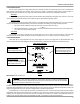
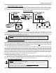
shock or product damage, remove all sources of power before installing or servicing. Figures 3 and 4 show generalized connections
only and are not intended to show all wiring, circuit protection and safety requirements for a photovoltaic electrical system.