
User's Manual

TransPondIT
®
for CENTRON
Installation Instructions
Models 915-120, 915-122
Blue Tower Communications Ltd www.bluetowercomms.com
US Office - One New Hampshire Ave, Suite 125, Portsmouth, NH 03801 Tel +1 603 766 1989
UK Office - Suite 1 Basepoint Business Centre, Aviation Park, Christchurch, Dorset BH23 6NW Tel +44 845 2300 156
© 2005 Blue Tower Communications Ltd. All rights reserved.
All company names, brand names, and product names are the property of their respective holder(s).
Blue Tower Communications Ltd reserves the right to change specifications, packaging, or other product information without notice. This publication could include technical inaccuracies or typographical errors.
CENTRON is a registered trademark of Itron (formerly Schlumberger Electricity, Inc.). P/N 72005510 IM 05
Description
The TransPondIT for CENTRON
®
is an AMR module that has been
designed specifically for use with the CENTRON solid-state electric meter.
The TransPondIT sends meter data via radio frequency (RF) signal to a
receiving unit: HandTrackIT
®
, FastTrackIT
®
or CellTrackIT
®
.
Note: Please refer to the Technical Reference Manual TransPondIT for
CENTRON Solid State Electric Meter for further information on the product.
Required Equipment
The following items are required for TransPondIT installation:
• CENTRON meter (see compatibility chart)
• Computer running Windows XP
®
or Windows 2000
®
.
• ConFigIT Electric (serial) [360-200-10]
• RS232 cable [320-310-10]
• ConFigIT cable [K442436-001] & connector [K42395-001]
• ConFigIT software PC version 6.5 or higher
Installation Instructions
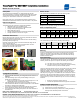
Remove the meters outer and inner covers being careful NOT to interfere
with the meters light pipe (see figures 1-3).
If applicable remove the black board-to-board connector and the existing
personality module (see figure 4).
Install the TransPondIT making sure that the PCB notches align with the
meter snaps (see figure 5).
Connect to the metrology board using the board-to-board connector.
Ensure that the connector is pushed fully home.
Refit both inner and outer meter covers.
Fig 1: Inner cover Fig 2: Remove cover Fig 3: Light pipe
Fig 4: Board-to-board connector Fig 5: Meter snap and PCB notch
Configuration Procedure
1. The TransPondIT should only be configured when the meter is un-
powered.
2. If the default settings (see ‘Factory Default Settings’ section) are
suitable for the installation then:
• Simply plug the meter into the meter socket and apply mains. The
TransPondIT derives its power from the meter.
3. If the default settings need to be changed, then please refer to the
Technical Reference Manual for Centron TransPondIT for more detailed
information on setting specific parameters.
4. Verify that the TransPondIT is transmitting valid data and is reported
with the appropriate receiving device from the desired location.
5. Verify that the reported reading corresponds to the visual indication on
the meters LCD.
Status Codes
The TransPondIT for CENTRON can report the following codes:
Error Code Description
1 Reverse energy flow detected
2 Metrology board failure
4 CAL pulse filtering
8 NVRAM Failure
Multiple errors are possible: ConFigIT PC software will decode errors.
Meter Compatibility Chart
Form 1S 2S 2S 3S 3S 4S 12S
Volts 120V 240V 240V 120V 240V 240V 120V
Class 100 200 320 20 20 20 200
Cat. No:
915-
120
915-
122
915-
122
915-
120
915-
122
915-
122
915-
120
Factory Default Settings
The TransPondIT is provided with the following default settings:
XPDR
ID
Meter
Reading
LCD test Display
format
Reverse
count?
Tx
Interval
UC
(04xxxxxx) 0 Enabled 5*1 Decrement
register
5s 55
Where: ‘XPDR ID’ = TransPondIT ID and ‘UC’ refers to the utility code.
Warning
Changes or modifications to the product not expressly approved by Blue
Tower Communications Ltd could void the user’s authority to operate the
equipment. See also Federal Communications Commission and Industry
Canada information below.
FCC Information
TransPondIT for CENTRON devices 915-120 and 915-122 comply with part
15 of the FCC Rules. The devices are approved for use only in CENTRON
electricity meters and operation is subject to the following two conditions:
(1) This device may not cause harmful interference and
(2) This device must accept any interference received, including
interference that may cause undesired operation.
This device has been tested and found to comply with the limits for a Class B
digital device, pursuant to Part 15 of the FCC Rules. These limits are
designed to provide reasonable protection against harmful interference in a
residential installation. This equipment generates, uses and can radiate
radio frequency energy and, if not installed and used in accordance with the
instructions, may cause harmful interference to radio or television reception,
which can be determined by turning the equipment on and off. The user is
encouraged to try to correct the interference by one or more of the following
measures:
• Reorient or relocate the receiving antenna
• Increase the separation between the equipment and receiver
Industry Canada Information
Operation is subject to the following two conditions:
(1) This device may not cause interference and
(2) This device must accept any interference, including interference
that may cause undesired operation of the device.