A-FRAME RESIN IN & OUT FLIP UP LADDER NE1222 NOTE • FOR SAFETY PURPOSES ALL LADDERS SHOULD BE SECURED BY ATTACHING THEM TO THE TOP LEDGE OF THE POOL. (See step 13 for details) • In order for the ladder to sit properly, it must be weighted in place using approximately 40 Lbs. of Sand. ( See step 9 for details) TOOLS REQUIRED • • • • • • • Small rubber mallet or hammer w/piece of wood Phillips head screwdriver or screw gun 5/16” Drill Bit Pliers Lubricant 40 lbs.
PARTS & HARDWARE A. UPPER STEP (8) (NEP2028) D. BOTTOM STEPS (2) C. PLATFORM B. LEGS (4) (NEP2025) (NEP2023) E. RIGHT AND LEFT STEP CONNECTORS (1) (1) NEP2026 (NEP2020) AND (1) NEP2022 G. HANDRAILS (2) (NEP2171) F. LOCKING CAPS (4) (NEP2014) H. LARGE BARRIER I. SMALL BARRIER (NEP2172) J. UPPER BRACE (NEP2174) 2 (NEP2173) K. LOWER BASE (NEP2175) L.
STEP 1 • Place the bottom step (D) on a level surface with indentations facing up. • Take leg (B) and stand upright (pointy side down). When installed on bottom step, the leg will need to have the raised areas facing inward. The raised area with the pre-drilled screw hole should be at the front of the ladder toward the top of the leg. • Place the left leg into the indentation on the left side of the step and push straight down until it clicks into place.
STEP 3 • Locate step connectors (E) which will be installed to hold the steps in place. There is a right and a left step connector, they are NOT interchangeable. The angle of the connector will allow for installation on only ONE side of the steps. Check the top of the connectors for the raised left and right markings. • Line up rounded area of left step connector with predrilled hole at top of leg. Remember, only one of these connectors will fit properly on the left side. STEP 3 CONT.
STEP 4 NOTE STEP 4 IS SIMILAR TO STEP 1 • Place the bottom step (D) on a level surface with indentations facing up. • Take leg (B) and stand upright (pointy side down). When installed on bottom step, the leg will need to have the raised areas facing inward. The raised area with the pre-drilled screw hole should be at the front of the ladder toward the top of the leg. • Place the left leg into the indentation on the left side of the step and push straight down until it clicks into place.
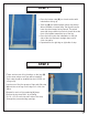
STEP 6 • Place the Lower Base (K) on a level surface. • Snap Large Barrier (H) into the groove on the lower base facing round edge. • Snap Small Barrier (I) into the groove on the lower base facing the straight side. • Slide Upper Brace (J) over Small Barrier as shown. • Slide Upper Brace (J) through the groove in the Large Barrier and push down lightly to secure. • Screw Lower Base of Entrapment Barrier into bottom step of the Inside Portion of the Ladder with (2) 10 x 1-1/4” screws.
STEP 6 CONT. • Screw Upper Brace of Entrapment Barrier into the third step of the Inside Portion of the Ladder with (2) 10 x 1-1/4” screws. (This is the side WITHOUT FLIP UP STEPS!) FOR 52” POOLS CONTINUE WITH STEP 7 FOR 48” POOLS SKIP TO STEP # 8 FOR 54” POOLS SKIP TO STEP # 9 STEP 7 52” POOLS • This ladder is designed to fit multiple pool heights. ONLY FOLLOW THIS STEP IF YOUR POOL HEIGHT IS 52”. • Locate the first line on the Handrail (G) of the ladder.
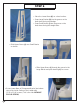
STEP 8 48” POOLS • This ladder is designed to fit multiple pool heights. FOR 48” POOLS, CUT HANDRAIL AT THIS SECOND LINE ONLY FOLLOW THIS STEP IF YOUR POOL HEIGHT IS 48”. • Locate the second line on the Handrail (G) of the ladder. • Using a hacksaw cut the Handrail evenly through both sides. • This Ladder is designed to fit multiple pool heights. ONLY FOLLOW THIS STEP IF YOUR POOL HEIGHT IS 48”. • Locate the leg (B) on both assembled sides of the ladder. • Find the line towards the top of the leg.
FOR 54” POOLS NO MODIFICATIONS ARE NECESSARY STEP 9 • Locate the interior portion of the ladder. This is the portion of the ladder that has the entrapment barrier attached to it. FILL LEGS WITH SAND USING A FUNNEL • Using a funnel fill both legs with sand. Use approximately 20 Lbs. of sand in each leg. STEP 10 • Lay one handrail (G) on a flat surface and push the connected dowels of the platform into the openings on the handrail until fully seated. Make sure treads of platform are facing upward.
STEP 10 CONT. • Center locking cap (F) over opening on side of handrail where platform was just attached. Using a rubber mallet or a hammer and a small piece of wood, tap on cap until the cap is flush with the Handrail • Repeat for each of the remaining (3) locking caps. STEP 11 • Coat the tops of the legs with Blue Seal O-Ring Lube or liquid soap and attach handrails by pushing them down over the legs.
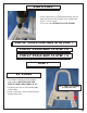
STEP 12 • Place assembled ladder inside the pool where you would like to enter and exit. The entrapment barrier should be inside of the pool. • Once the ladder is placed in the pool, tip the ladder forwards and backwards and side to side to release any air that may be trapped inside. NOTE When a Ladder is installed it is recommended that a Step Mat should be installed underneath. THIS ITEM IS SOLD SEPARATELY. STEP 13 • All pool ladders are required to be secured to the frame of the pool.
SAFETY INFORMATION • To avoid injury when lifting heavy or awkward loads, it is suggested that two people lift the object. • DO NOT use the pool entry system for any purpose other than that for which it is intended. • Maximum weight on steps should NOT EXCEED 250 lbs. WARNING Exceeding the recommended weight limit may cause the step to fail and may result in injury. LADDER SWINGS UP AND LOCKS IN PLACE NOTE You have purchased a Flip-up Safety Ladder.