ABOVE GROUND POOL FENCE ASSEMBLY INSTRUCTIONS Please Do N ot Hesitate to Contact Our Consumer H otline at 800-759-0 9 77 with Any Qu estions That May Arise During Assembly or Use of This P roduct! Ver.
THANK YOU! Thank you for purchasing this product. We work around the clock and around the globe to ensure that our products maintain the highest possible quality. However, in the rare case of issues during assembly or use of this product, please contact our Consumer Hotline at 800-759-0977 for immediate assistance before contacting your retailer. Please read the warranty information at the back of these assembly instructions for further details.
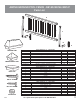
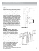
ASSEMBLY INSTRUCTIONS ABOVE GROUND POOL FENCE - NE145 / NE146 / NE147 Parts List D E C B A SUPPORT CAP BASE SUPPORT CAP NE145 BASE KIT “A” - 8 SECTIONS: DESCRIPTION QUANTITY End-Posts 2 NEP20293 A Support Assembly - Base 9 NEP20294 B Support Assembly - Support 9 NEP20295 C Posts 7 NEP20296 D Rail 16 NEP20297 E Spindles 96 NEP20298 Trim Kit (1) Post Cap, (1) Base Support Cap, (1) Support Cap, (2) Hole Plugs 9 bags NEP20299 Hardware Kit (18) #12 X 1” Screws, (136) #8 X 3/4”
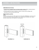
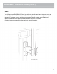
ASSEMBLY INSTRUCTIONS PREPARATION OF POOL 1. Inspect pool for irregularities that may interfere with the location of fence mounting brackets and posts. Locate skimmer to be sure it will not interfere with fence. 2. Recommended items need for installation: cordless or power drill with Phillips head screwdriver, saw, pencil and measuring tape. FENCE INSTALLATION STEP 1 Assemble mounting brackets. Slide support into mounting base (DIAGRAM 1-A).
ASSEMBLY INSTRUCTIONS (Cont.) STEP 2-A Install mounting bracket to each upright (DIAGRAM 2-A). When installing your fence, it is important that there is no more than a 4" gap between the pool’s top rail and the bottom rail of fence.
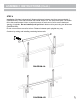
ASSEMBLY INSTRUCTIONS (Cont.) STEP 3 Install fence posts (DIAGRAM 3). Start by installing the two fence end-posts first. The end-posts are identifiable by having rail holes only on one side. Fence end-posts must be installed where fence will start and stop. Slide fence end-post onto the mounting bracket. Allow at least 1/2” between the post and the pool’s top cap.This will allow for easy installation of winter cover. Attach fence post to mounting bracket using four #8 screws.
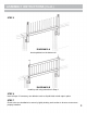
ASSEMBLY INSTRUCTIONS (Cont.) STEP 4 Installation of bottom horizontal rail. Measure distance between two fence posts and add 1" (DIAGRAM 4-A). Each side of bottom rail should extend 1/2” into each fence post. Cut bottom rail to this measurement. Note: cut equal amounts off each end of rail to ensure balanced spacing of spindles. Do not install top rail yet! Attach bottom rail to post using two #8 screws (DIAGRAM 4-B). Do not cut more than one rail at a time. Distance between pool uprights may vary.
ASSEMBLY INSTRUCTIONS (Cont.) STEP 5 DIAGRAM 5-A Insert spindles into the bottom rail. DIAGRAM 5-B Install top rail using instruction in Step 4. STEP 6 Insert all caps. If necessary, use adhesive such as Liquid Nails to hold caps in place. STEP 7 Check to be sure installation is secure by lightly shaking each section to be sure screws were properly installed.
5-YEAR LIMITED WARRANTY 1. The manufacturer extends this warranty to the original purchaser of this Above Ground Pool Fence. This warranty covers the Above Ground Pool Fence only. Other equipment such as uprights, toprails, ladders, slides, etc. are not supplied nor manufactured by Blue Wave Products and are not covered under this warranty. 2. This above ground resin fence is warranted to be free of manufacturing defects. This warranty is null and void if the design of this product is altered.
CLÔTURE DE PISCINE HORS SOL INSTRUCTIONS D’ASSEMBLAGE Contactez no tre service à la c lientèle au 800-75 9-0977 avec des que stions sur le montage ou l'utilisatio n de ce prod uit. Ver.
MERCI !! Merci d'avoir acheté ce produit. Nous travaillons 24 heures sur 24 et dans le monde entier pour nous assurer que nos produits conservent la meilleure qualité possible. Toutefois, dans les rares cas de problèmes lors de l'assemblage ou de l'utilisation de ce produit, veuillez contacter notre service d'assistance téléphonique aux consommateurs au 800-759-0977 pour obtenir une assistance immédiate avant de contacter votre détaillant.
ASSEMBLY INSTRUCTIONS CLÔTURE DE PISCINE HORS SOL - NE145 / NE146 / NE147 Liste des pièces D E C B A CAPUCHON DE SUPPORT CAPUCHON DE SUPPORT DE BASE NE145 BASE KIT “A” - 8 SECTIONS: DESCRIPTION QUANTITÉ PIÈCE NO.
INSTRUCTIONS DE MONTAGE PRÉPARATION DE LA PISCINE 1. Inspectez la piscine pour détecter les irrégularités susceptibles d'interférer avec l'emplacement des supports de fixation et des poteaux de la clôture. Localisez l'écumoire pour vous assurer qu'elle n'interfère pas avec la clôture. 2. Matériel recommandé pour l'installation : perceuse sans fil ou électrique avec tournevis à tête Phillips, scie, crayon et ruban à mesurer. INSTALLATION DE LA CLÔTURE Étape 1 Assemblez les supports de montage.
INSTRUCTIONS DE MONTAGE (Suite) ÉTAPE 2-A Installez un support de montage sur chaque montant (SCHÉMA 2-A). Lors de l'installation de votre clôture, il est important qu'il n'y ait pas plus de 4" d'espace entre le rail supérieur de la piscine et le rail inférieur de la clôture.
INSTRUCTIONS DE MONTAGE (Suite) ÉTAPE 3 Installer des piquets de clôture (SCHÉMA 3). Commencez par installer les deux poteaux de clôture en premier. Les poteaux d'extrémité sont identifiables par des trous de rail sur un seul côté. Les poteaux de clôture doivent être installés à l'endroit où la clôture commence et s'arrête. Faites glisser le poteau d'extrémité de la clôture sur le support de montage.
INSTRUCTIONS DE MONTAGE (Suite) ÉTAPE 4 IInstallation du rail horizontal inférieur. Mesurez la distance entre deux poteaux de clôture et ajoutez 1" (SCHÉMA 4-A). Chaque côté de la traverse inférieure doit s'étendre sur 1/2" dans chaque poteau de clôture. Coupez la traverse inférieure à cette mesure. Remarque : coupez des quantités égales à chaque extrémité du rail pour assurer un espacement équilibré des poteaux.
INSTRUCTIONS DE MONTAGE (Suite) ÉTAPE 5 ILLUSTRATION 5-A Insérer les broches dans le rail inférieur. ILLUSTRATION 5-B Installez le rail supérieur en suivant les instructions de l'étape 4. ÉTAPE 6 Insérez tous les capuchons. Si nécessaire, utilisez un adhésif tel que Liquid Nails pour maintenir les capuchons en place. ÉTAPE 7 Vérifiez que l'installation est bien fixée en secouant légèrement chaque section pour vous assurer que les vis ont été correctement installées.
GARANTIE LIMITÉE DE 5 ANS 1. Le fabricant étend cette garantie à l'acheteur original de cette clôture pour piscine hors sol. Cette garantie couvre uniquement la clôture pour piscine hors sol. Les autres équipements tels que les montants, les rails supérieurs, les échelles, les glissières, etc. ne sont pas fournis ni fabriqués par Blue Wave Products et ne sont pas couverts par cette garantie. 2. Cette clôture en résine hors-sol est garantie comme étant exempte de tout défaut de fabrication.