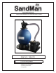
INCLUDES BASE FOR FILTER AND PUMP NE6150 / NE6170 TOOLS REQUIRED • Phillips head screwdriver • Flat head screwdriver • O-ring lube 6420
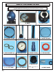
PARTS FOR SAND FILTER NOTE The quantity of parts and part numbers will vary for each filter. See breakdown on following page for model specific part lists. A. FILTER TANK B. BASE C. 6 WAY VALVE D. CLOSURE CLAMP E. STANDPIPE F. LATERALS (8) G. VALVE O-RING H. HOSE CLAMPS (6) I. PRESSURE GAUGE J. STRAIGHT FITTING (3) K. TEFLON TAPE N. DRAIN PLUG L. 3’ 1-1/2” HOSE 2 M. 6’ 1-1/2” HOSE (2) NOTE: Pre-installed on tank O.
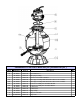
SANDMAN FILTER PARTS NE6150A (18") & NE6170A (22") REF # 1A 1B 2 3 4A 4B 5A 5B 6A 6B 7 8 9 Mrf Model # AC 18601 AC 22601 AC 22602 AC 18604 AC 18605 AC 22605 AC 18606 AC 22606 AC 18607 AC 22607 AC 18608 AC 18609 AC 08621RP Order # NEP2121 NEP2122 NEP2123 NEP2124 NEP2125 NEP2126 NEP2127 NEP2128 NEP2129 NEP2130 NEP2131 NEP2132 NEP2133 Descripton 18" sand filter base 22"sand filter base Drain plug assembly Lateral for 18" and 22" sand filter Center pipe & folding umbrella lateral holder for 18" sand filter C
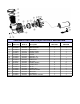
SANDMAN PUMP NE6150B/6170B PARTS BREAKDOWN KEY # MFR Part # 1 AC 81361 2 AC 81396 3 AC 81434 4 AC 81469 5 AC 81477 6 AC 81485 7A AC 81493 7B AC 81507 8 AC 81523 9 AC 81531 10 AC 81558 10 AC 81566 12 AC 81574 13 AC 81582 14 AC 81590 15 AC 81620 16 AC 81655 17 AC 84476 Order # NEP2134 NEP2135 NEP2136 NEP2137 NEP2138 NEP2139 NEP2140 NEP2141 NEP2143 NEP2144 NEP2145 NEP2146 NEP2147 NEP2148 NEP2149 NEP2150 NEP2151 NEP2152 Description PUMP LID PUMP LID O‐RING PUMP BASKET STRAINER CASING DIFUSSER O‐RING DIFUSSER
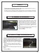
ASSEMBLY INSTRUCTIONS FOR SAND FILTER NOTE Filter is partially assembled; however, nothing has been properly tightened. DO NOT operate filter system without completing assembly instructions. STEP 1 • Using Phillips head screwdriver, remove the closure clamp (D) from the valve assembly. You only need to unscrew one side completely as it can be removed and reinstalled without unscrewing both screws. • Remove the valve (C) from the tank and place it to the side until instructed to reattach it.
STEP 2 • The filter and pump should be attached to the base prior to filling the filter with sand as it will be difficult to maneuver after the tank is full. • In order to attach your pump to the base, determine which of the two pumps shown below is most like your pump and follow the corresponding instructions for installation to the base. A.
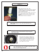
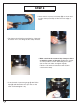
STEP 3 • Before filling tank with sand, cover standpipe with a plastic bag to prevent sand from entering standpipe. Secure in place with rubber band so it does not fall off. • Once bag is secured, place standpipe in the bottom of the sand tank. Make sure pipe is centered in tank BEFORE pouring sand into tank because you will NOT be able to move it once sand is in. NOTE Sand should be filled no less than 1/2 way up the tank and no more than 3/4.
STEP 3 — CONTINUED • Add filter grade sand (sold separately) to filter tank around standpipe. The approximate amount of sand necessary will vary based on the size filter you purchased. 18” Tank .... 110 Lbs. 22” Tank .... 220 Lbs. 26” Tank .... 360 Lbs. NOTE NEVER FILL SAND TANK MORE THAN 1/2 TO 3/4 OF THE WAY. Adding too much sand can cause weak return flow. • Remove plastic bag and fill tank with water until the tank is filled right below opening of standpipe.
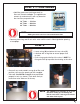
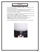
STEP 5 • Once valve is in place, hold clamp (D) as shown and position clamp around lip of filter and over edge of valve. • The clamp should sit flat around the lip of the tank and valve. If it is not sitting flat the clamp will leak. • Make sure that the screws of the clamp are lined up with the seams of the tank. Tighten two screws on clamp a little at a time. Alternating from side to side so that both sides are tighten equally. Failure to follow these instructions will result in a leak at the clamp.
STEP 6 • The valve ports are labeled “RETURN”, “PUMP” and “WASTE” with raised letters next to the openings. • Cover the threads of each straight fitting (J) with Teflon tape (K) and thread one fitting into each of the 1-1/2” threaded openings on the valve. • Attach one 6’ hose (M) to the bottom of the thru-wall skimmer and to the front of the pump with (2) hose clamps (H). • Clamp one end of 3’ hose (L) to the top of the pump and the other end to the threaded fitting on the “PUMP” port of the valve.
OPERATING YOUR FILTER NOTE Your filter cannot be run if the water is not at the proper level in the pool. Running the filter without water can cause serious damage to your pump and filter. • Prime filter prior to starting up filter system. DO NOT turn motor on until system has been primed, you can damage your pump. • Make sure water in pool is up to middle of skimmer(s) and that there is nothing blocking water flow from return(s) and skimmer(s) (i.e. plug, plate).
TROUBLESHOOTING LOW WATER FLOW SHORT FILTER CYCLES 1. Check skimmer and pump strainer baskets for debris. 1. Check for algae in pool and superchlorinate as required. 2. Check for restrictions in intake and discharge lines. 2. Be sure chlorine and pH levels are in proper range. Adjust as required. 3. Check for air leak in intake line (indicated by bubbles returning to pool). 4. Backwash filter. 5. Bring sand level in filter down to 1/2 full. 3. Check surface of filter sand for crusting or caking.
NE6150 & NE6170 One Year Sandman Filter System Warranty Registration Card 1745 Wallace Ave, Ste. B St. Charles, IL 60174 1. Sandman Filter System has a one year warranty against defects in materials and workmanship. To receive the warranty, the card must be filled out completely and returned. 2. Filter System must be returned with a receipt showing date of purchase, purchase price, and the dealer from which the cartridge was purchased. No warranty claim will be honored without a receipt.