DIGIMETER ELECTRONIC FLOWMETER PIPE FITTING INSTALLATION MANUAL SADDLE MACHINED IN-LINE BODY MOLDED TEE MOLDED IN-LINE BODY Blue-White R Industries, Ltd. 5300 Business Drive Huntington Beach, CA 92649 USA Phone: 714-893-8529 FAX: 714-894-9492 E mail: sales@blue-white.com or techsupport@blue-white.com Website: www.blue-white.
F-2000 1.0 Page 2 Temperature vs. Pressure Temperature 200°F (93.3°C) 190°F (87.8°C) 180°F (82.2°C) 170°F (76.7°C) 160°F (71.1°C) 150°F (65.6°C) 140°F (60°C) 130°F (54.4°C) 120°F (48.9°C) 110°F (43.3°C) 100°F (37.8°C) 90°F (32.2°C) 80°F (26.7°C) 70°F (21.1°C) 0 (0) 60 (4.1) 120 (8.3) 180 (12.4) 300 (20.7) 240 (16.5) PSIg (BAR) When mounted on Polypropylene and PVDF inline units When mounted on Molded PVC Tee or PVC pipe units Fig. 1 Note: Pressure and temperature limits are inversely proportional.
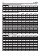
F-2000 Page 3 Molded Inline Bodies (Male NPT connection) - continued 1-1/2” - 2” pipe sizes - GPM (gallons per minute) Pipe Size (in.) 1-1/2 1-1/2 1-1/2 2 2 2 2 Pipe Sch. Flow Range # Inline Inline Inline 1 2 3 1 2 3 4 Inline Inline Inline Inline Flow Range (GAL/Min) 4.00 - 40.00 6.00 - 60.00 10.0 - 100.0 4.00 - 40.00 6.00 - 60.00 10.0 - 100.0 20.0 - 200.0 K-Factor (Pulse/GAL) 466.20 192.93 156.94 468.75 196.40 162.16 67.416 RATE 1 RATE 2 TOTAL 1 TOTAL 2 Rate Scale Factor (Sr) 12.8700 31.
F-2000 Page 4 3.0 PIPE INSTALLATION REQUIREMENTS 3.1 Flow Stream Requirements ! The F-2000 accuracy is based on steady, undisturbed flow with a fully developed turbulent flow profile. Pulsating, swirling and other disruptions in the flow stream will effect the meters accuracy. ! There are two basic types of flow profiles; turbulent and laminar (see figure 2). Turbulent flow exists when the speed of the fluid flowing in the pipe is nearly constant across the entire width of the pipe.
F-2000 Page 5 4.0 HOW TO INSTALL THE F-2000 The F-2000 was designed to be installed and operated by qualified personnel only. Do not attempt to install or operate the F-2000 if you are unsure. Seek qualified assistance. Please note that warranty coverage does not include damage due to misuse or improper installation. Mounting Location ! The F-2000 is designed to withstand outdoor conditions. A cool, dry location, where the unit can be easily serviced is recommended.
F-2000 5.0 Page 6 How To Install Your F-2000 Saddle Fitting The F-2000 saddle is designed to mount on smooth schedule 40 IPS pipe, schedule 80 IPS pipe(ASTM-D-1785), PN10 metric pipe or PN16 metric pipe (DIN 8062). The outside of the pipe must be clean, smooth and free of surface imperfections. The outside diameter must be as specified to ensure a leak free installation. The inside diameter must be as specified to ensure meter accuracy. H Pipe O.D. (Outside Diameter) L I.P.S.
F-2000 Page 7 Step 1 Drill The Mounting Hole ! Select an area on the pipe. Be sure the surface area of the pipe is clean and smooth. ! F-2000 can accurately measure flow either direction provided the minimum inlet and outlet conditions are met. ! Drill a 1-1/8" diameter hole through the center of the pipe wall. On horizontal installations, drill the hole as close to the vertical (12 O'clock) position as possible. Do not exceed 45O from vertical. See figure 5.
F-2000 6.0 Page 8 Installing The Machined In-line Fitting (PI) The machined in-line fittings consist of a meter body, two pipe adapter fittings (inlet and outlet), and two half union nuts. Pipe adapters are supplied with female American National Standard Taper Pipe Threads (NPT). The adapters are secured to the meter body with half union nuts and sealed with Viton O-rings. ! Select an area on the pipe as outlined in section 4.1.
F-2000 Page 9 7.0 Installing The Molded In-Line Fitting (MI) All molded in-line (MI) fittings have male American National Standard Taper Pipe Threads (MPT). ! Select an area on the pipe as outlined in section 4.1. ! The F-2000 can accurately measure flow from either direction provided the minimum inlet and outlet conditions are met. Section 3.1 ! Install the F-2000 as you would any other plastic pipe fitting. Be sure the inlet and outlet fittings are aligned properly.
F-2000 8.0 Page 10 How To Install Your F-2000 Molded PVC Fitting (AT) Note: Tee fittings are I.P.S. Pipe, Slip glue joints. Step 1 Select an area on the pipe as outlined in section 4.1. Step 2 Remove the F-2000 sensor from the tee fitting. Do not glue the Tee while the sensor is installed. Step 3 Install the F-2000 tee fitting as you would any other plastic pipe solvent weld (glue) fitting. Do not use too much glue.
F-2000 Page 11 Molded In-Line Body Parts List Saddle Parts List 1 2 3 Pipe Fitting 4 Replacement Part Numbers Complete Kit Ordering Numbers Machined Molded In-Line In-LinePipe PipeFittings Fittings- U.S. - U.S.(IPS) (IPS)M/NPT F/NPT Kit No 38M1 38M2 38F1 38F2 50M1 50M2 Item Part No . Description 1 76000-830 Alignment tool 2 91001-115 Saddle, 1-1/2” pipe (50mm) 91001-114 Saddle, 2” pipe (63mm) Description 3/8” MPT .800 - 8.000 GPM - PP 91001-116 Saddle, 3” pipe (90mm) 3/8” MPT .
F-2000 Page 12 Machined In-Line Block Parts 1 2 3 4 Pipe Replacement Part Numbers Item 1 Part No . Body .50” 2-20 GPM PP 76100-108 76100-105 76100-107 76100-104 Body .75” 4-40 GPM PP Body .75” .8-8 GPM PP Body 1.0” 6-60 GPM PP 3 4 Description 38P1 38P2 3/8” In-Line block, .8-8 GPM, PP 3/8” In-Line block, .4-4 GPM, PP 38K1 38K2 50P1 50P2 3/8” In-Line block, .8-8 GPM, PVDF 1/2” In-Line block, 2-20 GPM, PVDF 3/8” In-Line block, .