F-2000 MODEL RT INSTRUCTION MANUAL Blue-White R Industries, Ltd. 5300 Business Drive Huntington Beach, CA 92649 USA Phone: 714-893-8529 FAX: 714-894-9492 E mail: sales@blue-white.com or techsupport@blue-white.com Website: www.blue-white.
F-2000 Page 2 TABLE OF CONTENTS Section 1.0 Heading Features Page 3 2.0 Applications 3 3.0 Specifications 3 Physical Dimensional Drawing Temperature vs. Pressure Graph 3 4 4 4.0 Flow ranges 5 5.0 6.
F-2000 Page 3 1.0 FEATURES ! Battery powered rate and total ! Weather resistant enclosure (NEMA 4X) ! Extended battery life mode (screen blanks after 30 seconds) ! Corrosion resistant PVDF sensor ! Corrosion resistant ABS enclosure ! Easy to read, eight digit LCD display ! High accuracy ! Installs quickly on existing pipe ! Extended flow range ! Factory programmed ! Front panel security lockout ! Field programmable front panel push buttons ! Minimal maintenance required ! No pressure drop 2.
F-2000 3.2 Page 4 Dimensional Drawing 3.25 in. (82.55 mm) 4.00 in. (101.6 mm) BLUE-WHITE® INDUSTRIES F-2000 4.00 in. (101.6 mm) 8888.8888 MA BATCH # RATE TOTAL SETPOINT ENTER CLEAR SETPOINT CLEAR TOTAL Flow Monitoring System Fig. 1 3.3 Temperature vs. Pressure Temperature 200°F (93.3°C) 190°F (87.8°C) 180°F (82.2°C) 170°F (76.7°C) 160°F (71.1°C) 150°F (65.6°C) 140°F (60°C) 130°F (54.4°C) 120°F (48.9°C) 110°F (43.3°C) 100°F (37.8°C) 90°F (32.2°C) 80°F (26.7°C) 70°F (21.1°C) 0 (0) 60 (4.
F-2000 Page 5 IPS PIPES MOLDED INLINE BODIES Pipe Size 3/8” 3/8” 1/2” 1/2” 3/4” 3/4” 1” 1” 1-1/2” 1-1/2” 1-1/2” 2” 2” 2” 2” RANGE# 1 2 1 2 1 2 1 2 1 2 3 1 2 3 4 min - max operating flow range GPM .800 - 8.000 .400 - 4.000 2.00 - 20.00 .500 - 5.000 3.00 - 30.00 .800 - 8.000 5.00 - 50.00 2.00 - 20.00 4.00 - 40.00 6.00 - 60.00 10.0 - 100.0 4.00 - 40.00 6.00 - 60.00 10.0 - 100.0 20.0 - 200.
F-2000 5.0 Page 6 Mounting Options Rotating Display Step 1: Remove Two Screws Step 2: Rotate 90° Step 3: Re-attach Screws Fig. 6 Angle Mount on Horizontal Pipe Recommended Vertical 45° Acceptable 45° Acceptable Fig. 7 BR AC KE T F- 20 00 Panel Mount (92.0 ± H .032 .000 in. .80 .00 mm) H EX N U TS PA N EL C AP PL U G W AS ST U D ER S S 3.622 ± Fig. 8 Fig.
F-2000 Page 7 Optional Pipe and Wall Mount Adapter Kit Screw Wall Wall Mount Mounting Base Display Module ® BLUE-WHITE INDUSTRIES F-2000 ENTER CLEAR SETPOINT CLEAR TOTAL Flow Monitoring System Wire to Sensor Cap Plug Wall Screw Fig. 10 Clamp Pipe Mount Display Module Mounting Base Pipe ® BLUE-WHITE INDUSTRIES F-2000 ENTER CLEAR SETPOINT CLEAR TOTAL Flow Monitoring System Fig.
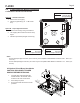
F-2000 6.0 Page 8 F-2000 Electrical Wiring Connections 6.1 Enclosure knock-out Instructions Option A: Option A: Conduit Connection 1 / 2-14 MPT Red Cap Plug (for pipe fitting) 1. Remove the red cap plug. 2. Install your pipe fitting (1/2 - 14 NPT male end). l rna w Vie e Int Option B: Liquid-Tight Connections 1. Remove knock-out(s) using a screwdriver. 2. Trim edge(s) with a knife and remove sharp edges. 3. Install the provided liquid-tight connector(s). Option B: 3/4 DIA.
F-2000 Page 9 6.3 Model RT Circuit Board Wiring CAUTION: DISCONNECT POWER SOURCE BEFORE SERVICING. Jumper Configuration Jumpers Function J1 Installed Battery Input (4 - 1.
F-2000 Page 10 6.4 Model FHXX and FCXX Sensor wiring RED Input Supply Voltage (+ 6 to 24 Vdc) BARE Signal Output (square wave) BLACK Ground (-) Model FHXX Note: Output type - current sinking type hall effect sensor (13.5mA max). Pull-up resistor is recommended. 5k ohm across red & bare wires. Approximately 10 to 350 Hz operating range. RED Signal Output (Sine wave) BLACK Ground (-) Model FCXX Note: Output type - AC sine wave. 100 mV peak to peak. 0.06 to 3.00 volts AC / 10uA to 500uA AC.
Page 11 7.0 HOW TO OPERATE THE F-2000 7.1 Theory of Operation F-2000 The MODEL RT is the base unit of the F-2000 flow monitoring system. Fluid flowing through the pipe causes the paddlewheel to spin. Pulses generated by the spinning paddlewheel are counted and multiplied by scaling factors. The resulting flow rate amounts and total flow amounts are displayed on the LCD readout.
F-2000 Page 12 7.2.2 What Features Are Available On The MODEL RT? ! Press ENTER to toggle between RATE and TOTAL display modes. The icon will RATE TOTAL light to indicate the active mode. ! Press and hold ENTER for at least 1.25 seconds to enter the programming mode. 0 00000 Allow twenty seconds to pass so the display will switch back to the readout RATE mode. See section 7.1. ! While the TOTAL mode is displayed, press CLEAR TOTAL to reset the total amount to TOTAL 0 zero.
F-2000 Page 13 Step 1 Where would you like your displayed flow rate decimal point located? Desired Location XXXXX XXXX.X XXX.XX XX.XXX X.XXXX Step 2 = = = = = = Dr (Decimal Rate Factor) 1 10 100 1000 10000 Note: Four decimal places maximum. Enter your Dr here. What time factor would you like to use in your measurement? Example: Per Minute = 60 seconds Per Hour = 3600 seconds Per Day = 86400 seconds Fill in the amount of seconds you desire here.
F-2000 Step 4 Page 14 Calculate your Rate Scale Factor (Sr) using the following formula. Dr from Step 1, Seconds from Step 2, K-Factor from Step 3. Example: Sr = Dr x Seconds Dr Seconds K-Factor K-Factor = 10 = 3600 = 63.52 Sr = 10 x 3600 63.52 Sr = 36000 63.52 Sr = 566.751 Write your Sr (Rate Scale Factor) number here. Step 5 Where would you like your displayed accumulated Total Decimal (Dt) point located? Desired Location = Dt (Total Decimal Factor) XXXXX XXXX.X XXX.XX XX.XXX X.
F-2000 Page 15 7.2.4 How Do I Program The MODEL RT? Note: While in the programming mode, if no buttons are pressed within twenty seconds, the programming mode is automatically exited without saving the input of the last screen. See page 18 for programming menu flow chart. Step 1 Entering the Rate Scale Factor. ! Press and hold down ENTER 000000 for at least 1.25 seconds. RATE ! Enter the Rate Scale Factor (Sr from Step 4, page 14).
F-2000 Step 5 Page 16 The Total Decimal Point screen is selected. 2 000000 ! The Total 2 screen is where you enter your Decimal Point Factor for your totalizer. TOTAL Use the information you calculated on Dt, on Page 14, Step 5. Move the decimal point by pressing the CLEAR TOTAL until ENTER the decimal point is in the desired location. Then press Step 6 . Ex. 00000 Off 3 The Front Panel Clear Total Button Enable / Disable screen is TOTAL selected.
F-2000 Page 17 Molded Inline Bodies (Male NPT connection) - continued 1-1/2” - 2” pipe sizes - GPM (gallons per minute) Pipe Size (in.) 1-1/2 1-1/2 1-1/2 2 2 2 2 Pipe Sch. Flow Range # Inline Inline Inline 1 2 3 1 2 3 4 Inline Inline Inline Inline Flow Range (GAL/Min) 4.00 - 40.00 6.00 - 60.00 10.0 - 100.0 4.00 - 40.00 6.00 - 60.00 10.0 - 100.0 20.0 - 200.0 K-Factor (Pulse/GAL) 466.20 192.93 156.94 468.75 196.40 162.16 67.416 RATE 1 RATE 2 TOTAL 1 TOTAL 2 Rate Scale Factor (Sr) 12.8700 31.
F-2000 7.
F-2000 Page 19 8.0 MAINTENANCE The F-2000 requires very little maintenance, however, some conditions will cause increased wear or possible damage to the unit. ! Periodically remove the sensor assembly from the pipe fitting and inspect the meter for signs of wear and obstructions. Clean the paddle of any foreign objects. Replace the paddle and axle if worn.
F-2000 Page 20 F-2000 Parts List Item 1 2 3 4 5 6 7 8 9 10 11 12 13 14 15 16 17 18 19 20 21 22 23 24 25 26 27 28 29 30 31 32 Part Number 70000-783 90003-021 90007-589 71000-238 71000-289 70000-290 90011-080 91001-280 76000-628 90006-550 90012-208 71000-356 90006-592 90010-227 71000-311 71000-316 90011-155 76001-149 76001-150 90006-593 90008-331 71000-294 70000-500 70000-589 90008-332 90008-340 90011-038 90011-092 90011-026 90008-333 90013-222 90008-254 90010-233 90008-330 90008-336 90008-337 71000-310
F-2000 Page 21 F-2000 Exploded View 27 28 25 26 24 23 31 30 SIZE AA BATTERY SIZE AA BATTERY 32 22 29 19 5 15 18 21 17 888 8.
Warranty ! Blue-White flowmeters are warranted to be free from defects in material and workmanship for 12 months from date of factory shipment. Warranty coverage is limited to repair or replacement of the defective flowmeter only.