SONIC-PRO d Series S4 Ultrasonic Flow Meter Installation and Operating Manual ProSeries 2 TWO-YEAR WARRANTY ProSeries by Blue-White Industries, Ltd. Industries,Ind. Ltd.
Page 1 Sonic-Pro Safety Precautions Thank you for purchasing the Sonic-Pro series S4 ultrasonic flowmeter. This instruction manual provides important information regarding the safe installation, operation and maintenance of the flowmeter. Please read it carefully before attempting to install or operate the meter. A copy of this manual should be kept by the operator. Extra copies of this manual are available from your supplier or directly from the manufacturer.
Page 2 Sonic-Pro 1.0 Product Overview The Sonic-Pro series S4 Ultrasonic Flow Meter can measure fluid flow in water and many other clean fluids with sound speeds that are similar to water. The meter measures fluid flow using the Transit Time method. The S4 ultrasonic sound transducers do not touch the process fluid and there are no moving parts. This method of flow measurement is safe, nonintrusive and requires little to no maintenance.
Page 3 Sonic-Pro 2.0 Flowmeter SPU Installation 2.1 Unpacking The Sonic-Pro Flowmeter is shipped with the following items: ! ! ! ! Sonic-Pro Flowmeter SPU (Signal Processing Unit) Sonic-Pro Inline Pipe Fitting Enclosure Mounting Hardware (not included in sensor mounted units) 2 mounting plates 4 mounting plate screws (10-32 x .50”) 2 wall mounting screws (#10 x 1.
Page 4 Sonic-Pro 3.0 Ultrasonic Transducer Installation Minimum Straight Pipe Length Requirements The Sonic-Pro’s sound wave beam is only affected by fluid that actually passes through the beam and therefore, the meter will not measure with high accuracy if the fluid velocity is not consistent across the entire pipe diameter.
Page 5 Sonic-Pro 4.0 Wiring Installation 4.1 Electrical Connections The meter must be powered by 15 to 28 volts DC. Depending on the model ordered, an AC/DC plug-in transformer may have been be supplied for this purpose. See the diagram below for wiring of output signals, communications signals and process control relays. The transducer cable length is factory fixed. Do not attempt to modify the length of these cables. Various cable lengths are available from the factory.
Sonic-Pro 4.4 Wiring Terminals Page 6 The terminal blocks are plug type capable of accepting 14 to 30 AWG wire.
Page 7 Sonic-Pro 5.0 Operation 5.1 Power On 1. If power is present on Terminal T1 pins 1 & 2, the meter is always powered on. 2. If power is removed from Terminal T1 pins 1 & 2, and 4 D-Cell batteries are installed on Terminal T1 pins 4 & 5, the meter will stay on (battery back-up). Under these conditions, the meter can be turned on/off by pressing and holding the front panel ENTER button for three seconds. 3.
Sonic-Pro 5.3 Menu Navigation 5.3.1 Selecting and Entering Menus 5.3.2 Selecting Optional Items 5.3.3 Inputting Data Page 8 The Configuration Menu From the RUN mode, press and release the ENTER button to enter the CONFIGURATION menu. The following menu will be displayed: Ÿ Press up arrow p or down arrow q to select menu items. The selected item will be highlighted. Ÿ Press right arrow u or ENTER to enter the selected menu. Ÿ Press left arrow t to go back one menu. Ÿ Notice the gray area.
Page 9 Sonic-Pro 6.0 Configuration The S4’s SPU can be used with a Paddle Wheel type sensor that outputs an AC Sine wave or an Ultrasonic type sensor. 6.1 Configure the SPU for a Paddle Wheel Sensor When using an AC Sine wave Paddle Wheel type flow sensor and pipe fitting, the installer must input the pipe fitting K-factor. The K-Factor is the total number of pulses output by the sensor per gallon of fluid flow for a specific pipe fitting. The K-factor is different for each pipe fitting.
Sonic-Pro 6.2.1 Measurement Units Menu Page 10 Select ENGLISH when entering the Pipe Outside Diameter and Pipe Wall Thickness dimensional data in Inches. Select METRIC when entering pipe the Outside Diameter and Pipe Wall Thickness dimensional data in millimeters. Note that the factory default units is INCHES. These dimensions are shown on the Calibration Detail label affixed to the pipe fitting: Meas. Units ENGLISH METRIC CALIBRATION DETAIL LABEL 6.2.
Page 11 Sonic-Pro 6.2.2.4 Fluid Flow Direction The relative flow direction is shown on the Calibration Detail label affixed to the pipe fitting. Transducer Model Mount Method Cable Length(ft) Flow Direction 6.2.2.5 Fluid Flow Direction Direction A -> B B -> A Each of the flow directions (A to B and B to A) have a Scaling Factor and either a positive or negative Zero Factor associated with it.
Sonic-Pro 6.2.4 Fluid Menu Page 12 The sound transducers are located in the S4 pipe fitting. They are carefully positioned at the factory for use with water at 68 degrees F which has a SOS (Speed Of Sound) of 1481 meters per second. (see page 28 for water SOS chart). The transducer placement cannot be adjusted in the field. As the fluid’s sound speed moves away from the target Fluid SOS, measurements become more difficult.
Page 13 Sonic-Pro 6.3 Configure the SPU Meter Settings In the Meter Settings menu, the data logging functions and the display features can be configured. Logging Meter Settings Log Interval(s) Enter Value 0.0000 Rate Set Point 1 Rate Set Point 2 0.0000 Enter Value 0.0000 Enter Value Tot. Set Point 1 Tot. Set Point 2 0.0000 Enter Value 0.0000 Enter Value Tot. Set Point 3 Tot. Set Point 4 Enter Value 0.0000 Enter Value 0.0000 Enter Value Tot. Set Point 5 0.
Sonic-Pro 6.3.1 Logging Menu Page 14 Data logs are stored in the meter’s internal memory in a space delimited .TXT file that can easily be copied to a removable USB flash drive located on the main circuit board. Each log file includes the date and time, the flow rate (FR) and the flow total (TL). A total of 191,800 logs can be stored. 2013/12/29 09:15:00 FR 0.0000 TL 0.00 The Log Interval determines the number of seconds from 1 - 999,999 that the meter will wait between logs.
Page 15 Sonic-Pro 6.3.
Page 16 Sonic-Pro 6.3.2.2 Totalizer Menu In the Totalizer menu, the Volume Units may be selected from a list. A custom volume unit may be created by selecting FR Custom V/Gal and entering the number of gallons in the custom volume. The Fl. Total Decimal decimal point location may be set to a maximum of 5 digits. Totalizer Volume Units Fl. Total Decimal 6.3.2.3 Flow Average Setting Enter Value 0 U.S. Gallons Ounces U.S. Barrels Liq. U.S.
Page 17 Sonic-Pro 6.3.2.9 Sleep Timer To conserve power, the S4 can be configured to “sleep” from 3 to 268 seconds per cycle. At the end of each sleep cycle, the meter will “wake” for the number of seconds (from 2 to 10 seconds) as configured in the Flow Average feature, record data, and then return to sleep. During the “wake” period, the display will remain blank.
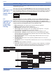
Sonic-Pro 6.4 Configure the SPU Output Settings Output Settings Page 18 In the Output Settings menu, the Analog 4-20mA, Pulse 0-1000 Hz, Contact Closures and the Anybus Communications module functions can be configured. Analog 4-20mA Rate at Min Curr. Enter Value Min Analog O/P Enter Value Rate at Max Curr. Enter Value Max Analog O/P Enter Value Rate at Min Freq. Enter Value Min Frequency Enter Value 0.0000 4 0.0000 20 Pulse 0-1000 0.
Page 19 Sonic-Pro 6.4.1 Analog 4-20mA Output Menu An analog current output signal can be programmed within the range of 4-20mA. Specify the flow rate at a minimum current (Rate at Min Curr.) and the corresponding minimum analog current (Min Analog O/P). Specify the flow rate at a maximum current (Rate at Max Curr.) and the corresponding maximum analog current (Max Analog O/P). The flow rates must not be the same.
Sonic-Pro 6.4.3 Contact Closure Relay Output Menu Page 20 The S4 has two Form C relays. Each can be independently configured to energize when one of the following conditions are met: ! A specific Flow Rate value is displayed, used for high, low or high/low range alarms. ! An Accumulated Total value has been measured. Used for triggering external equipment when a configured batch amount is reached. ! A FAULT has occurred.
Page 21 Sonic-Pro 6.4.3.1 CC Assigned to Monitor Totalizer When in the Relay A or Relay B menu, selecting and then exiting the Monitor Totalizer menu will assigned that relay to monitor the accumulated to flow value. The following functions are possible: ! Set a Batch Amount total flow value which when reached, will energize the relay. ! Set the Contact Timer(s) for the number of seconds (0-999) that the relay will remain energized.
Page 22 Sonic-Pro Select the module being used and enter the Port Address (for Profibus DPV or Modbus RTU modules) or the IP ADDRESS ( for Modbus TCP, Industrial Ethernet/IP or Profinet IO modules. Anybus Type Profibus DPV1 Modbus RTU Modbus TCP Ethernet Profinet None Address Profibus DPV1 Enter Value Modbus RTU Enter Value Modbus TCP IP SET 0 0 192.168.234.123 OK Ethernet CANCEL IP SET 192.168.234.123 OK Profinet CANCEL IP SET 192.168.234.
Page 23 Sonic-Pro 6.5 Configure the Clock In the Clock menu, use the right arrow u or left arrow t to highlight the Year, Month, Day, hour, or minute. Change the highlighted value using the up arrow p or down arrow q button. To sve the entries, highlight OK and press ENTER. The clock is powered by a supercapacitor, which is continuously charging while the meter is powered, rather than a battery. It never has to be replaced. Clock CLOCK SET 2013/07/24 14:31 OK 6.
Sonic-Pro 6.7.1 Password Page 24 The S4 is shipped from the factory with the default password 0000. If a new password is not configured, the meter will allow saving changes to the configuration at the main menu. Configuration Run Save Config A user defined four digit password can be entered to replace 0000. Change Password Change Password New Pass.: 1234 Confirm Pass.: 1234 OK CANCEL Once a new password has been configured, it must be entered to allow saving any changes made to the configuration data.
Page 25 Sonic-Pro 7.0 Specifications _________General Operation__________ _______SPU (Signal Processing Unit)_______ Measuring Principle Enclosure Ultrasonic - Transit Time. NEMA 4X (IP66), Powder coated aluminum, SS clamps and hardware. Dimensions: 7.24H x 6.69W x 3.11D inches (184H x 170W x 79D mm) Weight 3.7 lb. (1.7 Kg.) Fluid Types Water to 5% (0 to 50,000 ppm) particulate. Mounting Fluid Velocity Range 0.5 to 30 feet per second (0.
Page 26 Sonic-Pro 7.1 Model Number System Sonic-Pro S4 Part Number Matrix Signal Processing Unit (SPU) - Display S4 Sonic-Pro Base model Communications Options D Industrial Ethernet/IP E Modbus RTU F Modbus TCP/IP G PROFINET RT/IO H PROFIBUS-DPV1 X Standard 4-20mA and High Speed Pulse output only Input Power (15 - 30 VDC required - all units include D cell battery pack, 4 D cell batteries are not included) 0 Without power supply (customer supplies 15-30 VDC) 1 U.S.
Page 27 Sonic-Pro 7.2 Sound speed data Water Sound Speeds Temp OC Temp OF Sound Speed (meters/sec) 0 32 1403 5 41 1427 10 50 1447 20 68 1481 30 86 1507 40 104 1526 50 122 1541 60 140 1552 70 158 1555 80 176 1555 90 194 1550 100 212 1543 ProSeries by Blue-White Industries, Ltd. Industries,Ind. Ltd.
Page 28 Sonic-Pro 7.3 Dimensional Drawings Sonic-Pro SPU 3.11 in 79 mm 6.69 in 170 mm 8.00 in 203 mm .35 in 9 mm 3.14 in 80 mm 6.52 in 166 mm 3.2 in 81 mm 2.5 in 64 mm 6.23 in 158 mm 7.24 in 184 mm 1.24 in 31 mm .58 in 15 mm .81 in 21 mm 1.50 in 38 mm TYP. .70 in 18 mm .86 in 22 mm 6.52 in 166 mm Sonic-Pro Inline Pipe Fittings 15.36in 39.0cm 12.78in 32.45cm OW E OL OL A OW C B D Flanged Fittings NPT Fittings Pipe Size OL OW A B C Pipe Size OL OW D E 2" 7.47in [18.
Page 29 Sonic-Pro 7.4 Menu Flow Chart Configuration Paddle Wheel K-Factor Enter Value Run XDCR Settings Meas. Units ENGLISH METRIC Transducer Model 0.0000 Save Config Mount Method C I J Enter Value V W Cable Length(ft) Enter Value Flow Direction Direction Settings 0.0000 Pipe Pipe Outside Dia. A -> B B -> A 0.0000 Scaling(A->B) Zero(A->B) Zero Value(A->B) Sign(A->B) Positive Negative A -> B B -> A Enter Value 0.0000 Pipe Wall Thick.
Page 30 Sonic-Pro Output Settings Analog 4-20mA Rate at Min Curr. Enter Value Min Analog O/P Enter Value 0.0000 4 Rate at Max Curr. Enter Value Max Analog O/P Enter Value 0.0000 20 Pulse 0-1000 Rate at Min Freq. Enter Value Min Frequency Enter Value 0.0000 High Trigger A Enter Value High Release A Enter Value Low Trigger A Enter Value Low Release A Enter Value Time(s) A Enter Value Monitor Totalizer Batch Amt.
Limited Warranty ! Blue-White Sonic-Pro flowmeters are warranted to be free from defects in material and workmanship for 24 months from date of factory shipment. WARRANTY COVERAGE IS LIMITED TO REPAIR OR REPLACEMENT OF THE DEFECTIVE FLOWMETER ONLY. UNDER NO CIRCUMSTANCES SHALL BLUE-WHITE BE LIABLE FOR ANY CONSEQUENTIAL OR INCIDENTAL LOSES OR DAMAGES THAT SHOULD ARISE FROM THE USE OF THE FLOWMETER AND IN NO EVENT SHALL THE COMPANIES LIABILITY EXCEED THE PURCHASE PRICE PAID BY THE PURCHASER FOR THE PRODUCT.