
Owner's manual

Page 9
Sonic-Pro
6.0 Configuration
6.2
Configure the
SPU for an
Ultrasonic
Inline Pipe
Fitting
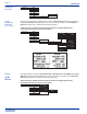
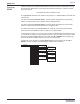
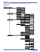
When using Ultrasonic Transducers (XDCR), if the SPU and the Ultrasonic Inline Pipe
Fitting was shipped from the factory as a single model number, the SPU is pre-configured
with the proper model number and calibration constants shown on the calibration label
attached to the pipe fitting. If the pipe fitting was sold separately, the SPU will need to be
configured with the following data shown on the calibration label:
1. Measurement Units. The default value for all inline fittings is ENGLISH.
2. Model. The default value for all inline fittings is “C”.
3. Mount Method. The default value for all inline fittings is “V”.
4. Cable Length. Enter the length in feet. The available cable lengths are: 1 foot (SPU
mounted directly on the pipe fitting), 10, 25, 50 or 100 feet.
5. Flow Direction -> Direction. The default value for all inline fittings is “A -> B”.
6. Flow Direction -> Settings. Each flow direction has a unique SCALING and ZERO
VALUE number shown on the pipe fitting calibration label. Note that the ZERO number
may be POSITIVE or NEGATIVE.
7. Pipe Outside Diameter. Shown on the pipe fitting calibration label. Do not use your
inlet/outlet pipe size.
8. Pipe Wall Thickness. Shown on the pipe fitting calibration label. Do not use your
nominal pipe size.
9. Pipe Material. Shown on the pipe fitting calibration label. Do not use your inlet/outlet pipe
material.
10. Fluid Type. Select WATER or CUSTOM.
11. Fluid SOS. If WATER is selected, it is not necessary to input a fluid SOS. If “CUSTOM”
fluid type is selected, the Speed of Sound (SOS) for the custom fluid must be entered
manually. Note that the SOS must be within the pipe fitting’s SOS range.
Configuration
Run
Save Config
Paddle Wheel
XDCR Settings
Meas. Units
METRIC
Transducer
Model
I
ENGLISH
C
J
Mount Method
W
V
Pipe
Pipe Outside Dia.
Enter Value
Pipe Wall Thick.
Enter Value
Pipe Material
Custom
Pipe SOS
0.0000
Enter Value
Fluid Fluid Type
Fluid SOS
Water
Cable Length(ft)
Enter Value
Flow Direction
Settings
Direction
B -> A
A -> B
Zero(A->B)
Scaling(A->B)
Enter Value
Sign(A->B)
Zero Value(A->B)
Positive
B -> A
A -> B
Enter Value
Zero(B->A)
Scaling(B->A)
0.0000
Enter Value
Sign(B->A)
Zero Value(B->A)
0.0000
Enter Value
10
0.0000 0.0000
0.0000
0.0000
HDPE
Custom
0000
Enter Value
Negative
Positive
Negative
6.1
Configure the
SPU for a
Paddle Wheel
Sensor
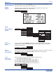
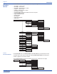
The S4’s SPU can be used with a Paddle Wheel type sensor that outputs an AC Sine wave or
an Ultrasonic type sensor.
Configuration
Run
Save Config
Paddle Wheel
K-Factor
Enter Value
0.0000
When using an AC Sine wave Paddle Wheel type flow sensor and pipe fitting, the installer
must input the pipe fitting K-factor. The K-Factor is the total number of pulses output by the
sensor per gallon of fluid flow for a specific pipe fitting. The K-factor is different for each pipe
fitting. See the paddle wheel sensor’s instruction manual for a list of pipe fitting K-factors.
Page 10
Sonic-Pro
6.2.1
Measurement
Units
Menu
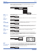
Select ENGLISH when entering the Pipe Outside Diameter and Pipe Wall Thickness
dimensional data in Inches. Select METRIC when entering pipe the Outside Diameter and
Pipe Wall Thickness dimensional data in millimeters.
Note that the factory default units is INCHES. These dimensions are shown on the
Calibration Detail label affixed to the pipe fitting:
Meas. Units
METRIC
ENGLISH
6.2.2
Transducer
Menu
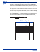
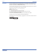
There are three transducer MODELS available to select. When using the S4 Inline Pipe
Fitting/Transducer, select model C. See the model number ordering matrix for additional
transducer model options.
6.2.2.1
Transducer
Model
Transducer
Model
I
C
J
6.2.2.2
Transducer
Mount Method
Transducer
Model
Mount Method
W
V
The transducers are factory set inside the pipe fitting and cannot be moved. Select the mount
method that is shown on the Calibration Detail label affixed to the pipe fitting.
Transducer
Model
I
C
J
Mount Method
W
V
Cable Length(ft)
Enter Value
Flow Direction
Settings
Direction
B -> A
A -> B
Zero(A->B)
Scaling(A->B)
Enter Value
Sign(A->B)
Zero Value(A->B)
Positive
B -> A
A -> B
Enter Value
Zero(B->A)
Scaling(B->A)
Enter Value
Sign(B->A)
Zero Value(B->A)
Enter Value
10
0.975 0.455
Negative
Positive
Negative
0.975
0.455
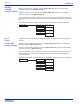
6.2.2.3
Transducer
Cable Length
Transducer
Model
Mount Method
Cable Length(ft)
Enter Value
10
Enter the transducer cable length. The available length options are:
1 = Sensor Mounted Display (no cable)
10 = 10 ft cable, transducer cable model number option “A”
25 = 25 ft cable, transducer cable model number option “B”
50 = 50 ft cable, transducer cable model number option “C”
100 = 100 ft cable, transducer cable model number option “D”
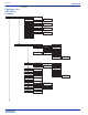
CALIBRATION DETAIL LABEL
Industries, Ltd.
Industries, Ltd.
ProSeries
by Blue-White Ind.
d
Industries, Ltd.
Industries, Ltd.
ProSeries
by Blue-White Ind.
d