
Owner's manual

Page 19
Sonic-Pro
Page 20
Sonic-Pro
6.4.1
Analog
4-20mA
Output Menu
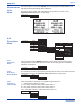
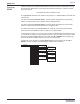
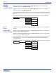
An analog current output signal can be programmed within the range of 4-20mA.
Specify the flow rate at a minimum current (Rate at Min Curr.) and the corresponding
minimum analog current (Min Analog O/P).
Specify the flow rate at a maximum current (Rate at Max Curr.) and the corresponding
maximum analog current (Max Analog O/P).
The flow rates must not be the same. The current for the high flow rate may be smaller than
the current for the low flow rate in which case, the current will decrease with increasing flow
rate.
Flow rates are mapped to currents using a straight line through the two points specified.
Analog 4-20mA
Rate at Min Curr.
0.0000
Enter Value
Min Analog O/P
4
Enter Value
Rate at Max Curr.
0.0000
Enter Value
Max Analog O/P
20
Enter Value
6.4.2
Pulse
0-1000 Hz
Output Menu
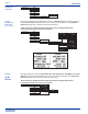
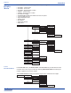
A digital pulse output signal can be programmed within the range of 0-1000 Hz (pulses per
second).
Specify the flow rate at a minimum frequency (Rate at Min Freq.) and the corresponding
minimum frequency (Min Frequency).
Specify the flow rate at a maximum frequency (Rate at Max Freq.) and the corresponding
maximum frequency (Max Frequency).
The flow rates must not be the same. The frequency for the high flow rate may be smaller
than the frequency for the low flow rate in which case, the frequency will decrease with
increasing flow rate.
Flow rates are mapped to frequencies using a straight line through the two points specified.
Pulse 0-1000
Rate at Min Freq.
0.0000
Enter Value
Min Frequency
0
Enter Value
Rate at Max Freq.
0.0000
Enter Value
Max Frequency
1000
Enter Value
6.4.3
Contact
Closure
Relay
Output Menu
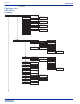
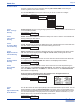
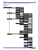
The S4 has two Form C relays. Each can be independently configured to energize when one
of the following conditions are met:
! A specific Flow Rate value is displayed, used for high, low or high/low range alarms.
! An Accumulated Total value has been measured. Used for triggering external equipment
when a configured batch amount is reached.
! A FAULT has occurred.
Contact Closure
Relay A
Monitor Flow Rate
High Trigger A
0
Enter Value
High Release A
0
Enter Value
Low Trigger A
0
Enter Value
Low Release A
0
Enter Value
Time(s) A
0
Enter Value
Monitor Totalizer
Batch Amt. A
0
Enter Value
Contact Timer(s) A
0
Enter Value
Faults A
Relay B
Monitor Flow Rate
High Trigger B
0
Enter Value
High Release B
0
Enter Value
Low Trigger B
0
Enter Value
Low Release B
0
Enter Value
Time(s) B
0
Enter Value
Monitor Totalizer
Batch Amt. B
0
Enter Value
Contact Timer(s) B
0
Enter Value
Faults B
None A
None B
Relay B
Monitor Flow Rate
High Trigger B
0
Enter Value
High Release B
0
Enter Value
Low Trigger B
0
Enter Value
Low Release B
0
Enter Value
Time(s) B
0
Enter Value
None B
6.4.3.1
CC Assigned to
Monitor Flow Rate
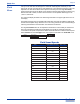
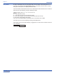
When in the Relay A or Relay B menu, selecting and then exiting the Monitor Flow Rate
menu will assigned that relay to monitor the rate of flow. The following functions are possible:
! Set a High Trigger flow rate value which when measured, will energize the relay.
! Set a High Release flow rate value which when measured, will de-energize the relay.
! Set a Low Trigger flow rate value which when measured, will energize the relay.
! Set a Low Release flow rate value which when measured, will de-energize the relay.
! Set a Time (s) in seconds (0-999) to delay energizing the relay when it is triggered.
When either of the relays are energized, the display back-light will turn blue.
When both the trigger and release values are configured for the same value, the relay will
latch. The user must press the ESC button to clear a latched relay.
Industries, Ltd.
Industries, Ltd.
ProSeries
by Blue-White Ind.
d
Industries, Ltd.
Industries, Ltd.
ProSeries
by Blue-White Ind.
d