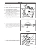
SET-UP Equipment set-up 1. Remove crate top and sides. 2. Remove upper handle bar assembly and lay aside. HARDWARE 3. Open bag containing loose hardware. WASHERS (2) COTTER PINS (2) 4. Using four (4) screws, flat washers and nuts attach the upper handle bar assembly to lower handle bar assembly. See Figure 1. UPPER HANDLE BAR ADJUSTING ROD NOTE: Handle fit is tight. When aligning holes use a tapered type pilot to help align holes (i.e. punch or phillips style screw driver). COTTER PIN (1) 5.
SET-UP 8. Attach the yoke to the brake’s top mounting hole using the clevis pin and cotter pin. Make sure the rod is positioned in the bracket as shown in Figure 4. NOTE: Adjust the brake before inserting hair pin. To engage brake, pull back on handle until brake rod assembly goes “over center” and locks the brake ON. Turning the yoke clockwise shortens the rod tightening the grip on the brake disc by the brake pads. counterclockwise loosens the clamping force.
SET-UP ENGINE THROTTLE CONTROL LEVER 14. Insert “L” end of throttle cable into the outside hole of the engine throttle control lever. Figure 7. THROTTLE CABLE FORWARD FIGURE 7 15. Attach the throttle cable to the engine using the double wire clamp removed in step nine. Figure 8. 16. Test throttle control by pulling back throttle handle on console. Throttle arm on engine should be pushed completely forward. Cable should not slip in clamp when doing this test. 17.
CONTROLS Presentation Congratulations on your choice of an exceptionally high quality product. This operator’s manual describes the BlueBird stump grinder. The machine is equipped with a 13 hp Honda fourcycle engine. Main components and operating controls 8 9 5 6 10 11 4 8 3 5 1 7 1. Handle 7. Engine 2. Dead man’s grip bar 8. Rear lifting handle 3. Brake lever 9. Adjustment bar for the handle 4. Belt guard for the cutter drive 10. Throttle 5. Front lifting handle 11. Engine switch 6.
CONTROLS Engine Exterior engine components and controls. 1. Throttle 2. Starter 3. Starter handle 4. Fuel valve 5. Choke control 6. Air filter 7. Spark plug 10 8. Muffler 8011-126 9. Oil dipstick 10. Oil drainage 11. Oil level guard 12. Engine switch - disconnected use switch on handle bar 14 13 13. Fuel tank 14. Fuel filler cap 12 11 9 8011-273chg Throttle The lever on the engine is normally not used. It is connected to the throttle on the handle.
CONTROLS Starter The starter is of the magnapull type with spring return. To replace the return spring or starter cord, contact an authorized service workshop. Starter handle Misuse of the starter handle can damage the starter. Do not twist the starter cord around your hand. Pull out the handle slowly until the gears mesh. Do not pull out the starter cord completely and do not let go of the starter handle when extended.
CONTROLS Spark plug The engine spark plug is hidden under the ignition cable shoe. When performing service, it is important that the engine cannot start accidentally. For this reason, always remove the ignition cable shoe from the spark plug. To avoid pulling the cable, the cable shoe is equipped with a special handle; see the illustration. Type of spark plug, see “Technical data”. Service instructions, see “Maintenance/Electrical system”.
CONTROLS Fuel tank Underneath the tank, there is a fuel filter combined with the fuel valve. The tank volume is 1.72 Gal. (6.5 liters) Fueling Read the safety instructions before fueling. Keep the fuel and fuel tank clean. Avoid filling the machine with dirty fuel. Make sure the fuel cap is properly tightened and the gasket is not damaged, particularly before washing the machine. Use unleaded gasoline with minimum 86 octane rating. Never use gasoline mixed with two-cycle oil.
CONTROLS Throttle . The lever controls engine speed. With the lever down, the engine runs at idle and functions as start position. When the engine speed increases, the centrifugal clutch drive automatically engages the cutting wheel. On/Off Engine switch on the panel The ON/OFF engine switch can be used to stop the engine. The illustration shows the toggle switch in the OFF position (short circuited electrical system).
OPERATION Starting the engine Check that all daily maintenance as described in the maintenance schedule has been performed. Check that there is sufficient fuel in the tank. Fuel valve Open the fuel valve. Place the lever all the way to the right. FUEL VALVE 8011-182 Choke control When starting the engine warm, the lever should be in the right position; see the illustration. When starting the engine cold or partially warm, place the lever completely or partly to the left.
OPERATION Engine switch on the handle Set the toggle switch to ON. Dead man’s grip bar Hold in the bar for the dead man’s grip against the handle. 8011-185 Starter handle The dead man’s grip must be pressed in when starting the engine. Misuse of the starter handle can damage the starter. DO NOT twist the starter cord around your hand. Pull out the handle slowly until the gears mesh. Then give a sharp pull on the starter handle.
OPERATION Normal shutdown Throttle Set the throttle to SLOW/DISENGAGE. . If the engine has been running full out, let it run easily for about 30 seconds to 1 minute at low speed. DO NOT let front of unit touch ground until you are sure cutting wheel has stopped turning. Engine switch Wait at least 20 seconds, until the blade has stopped. Set the toggle switch to OFF. Make sure that the blade is resting against the ground and has stopped completely before doing anything.
OPERATION Before you start Dig away the earth and remove any stones near the tree stump that may interfere with your work. Check that the ground is free of foreign objects, such as electrical cables, barbed wire, etc. Cut or trim the stump as necessary using a power saw. • Review all of the machine’s safety decals. 8011-141 • Use a hard hat, ear and eye protection. A mesh visor alone does not provide sufficient eye protection; supplement with protective glasses.
OPERATION Using your stump grinder WARNING! NEVER allow the blade to touch the ground until it has stopped turning. 1. Place the cutting blade near the top front edge of the tree stump. 8011-201-chg 2. Set the brake to lock position. 3. Set the throttle to SLOW (START) 4. Set engine switch on handlebar to ON. 28 . DISENGAGE.
OPERATION 5. Tilt the machine on its wheels, lifting the cutting wheel off the ground. 8011-202chg 6. Hold in the dead man’s grip bar and start the engine. 7. Allow the engine to warm up for two minutes at idle before grinding. 8011-127 8011-185 8. Set the throttle to FAST to ENGAGE clutch. . IMPORTANT INFORMATION If the cutting wheel is too low, the machine may start to “climb” over the stump and become unstable. 9. Place the middle of the cutting wheel approximately one inch (2.
OPERATION 11. Before moving the machine forwards, you should ensure that the cutting wheel is above the ground and located on either side of the stump. Move the machine forward by releasing the brake, pushing it forward, activating the brake again and repeating steps 9 and 10. 12. Repeat steps 9 through 11 until the upper portion of the stump has been removed. DO NOT cut deeper than ground level at this stage. 13. Set the throttle to SLOW/(START) DISENGAGE and wait until the cutting wheel stops rotating.