
Installation Guide


www.bluegrassliving.com
15200490-01A
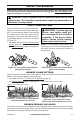
Log #1
Log #2
Log #4
Log #5
Log #3
Rear Plate
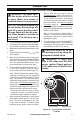
PRESSURE TESTING HEATER GAS CONNECTIONS
INSTALLING LOGS
Figure 17 - Installing Log #1
Figure 18 - Installing Logs #2 and #3
Figure 19 - Installing Log #3 & #4
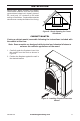
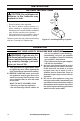
Figure 16 - Stove Cabinet
(Brick liner not shown)
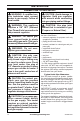
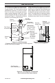
INSTALLATION
1. Open equipment shuto valve (see Figure
13, page 14).
2. Open main gas valve located on or near
gas meter for natural gas or open propane
supply tank valve.
3. Make sure control knob of heater is in the
OFF position.
4. Check all joints from equipment shuto
valve to control valve (see Figure 14 or
15, page 14). Apply a noncorrosive leak
detection uid to all joints. Bubbles form-
ing show a leak.
5. Correct all leaks at once.
6. Light heater (see Lighting Instructions on
page 17). Check all other internal joints
for leaks.
7. Turn o heater (see To Turn O Gas Ap-
pliance, page 18).
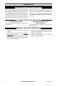
WARNING: Failure to posi-
tion the parts in accordance
with these diagrams or failure
to use only parts specically
approved with this heater may
result in property damage or
personal injury.
CAUTION: After installation,
and periodically thereafter,
check to ensure that no ame
comes in contact with any log.
With the heater set to high, check
to see if ames contact any log. If
so, reposition logs according to
the log installation instructions
in this manual. Flames contact-
ing logs will create soot.
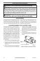
1. Install log #1 on the rear plate as shown
in Figure 17.
2.
Install logs #2 and #3 as shown in Fig-
ure 18.
3. Install log #4 and log #5 as shown in
Figure 19.
IMPORTANT: Make sure logs do not cover
any burner ports. It is very important to install
the logs exactly as instructed. Do not modify
logs. Use only logs supplied with heater.