VENT-FREE GAS FIREPLACE INSERT OWNER’S OPERATION AND INSTALLATION MANUAL MODEL FDF300R SKU #170032 This insert can be used in the mantel and fireplace systems CM300-1 WARNING: If the information in this manual is not followed exactly, a fire or explosion may result causing property damage, personal injury or loss of life. — Do not store or use gasoline or other flammable vapors and liquids in the vicinity of this or any other appliance. — WHAT TO DO IF YOU SMELL GAS • Do not try to light any appliance.
TABLE OF CONTENTS Safety......................................................... 3 Specifications............................................. 4 Qualified Installing Agency......................... 5 Product Features........................................ 5 Local Codes............................................... 5 Unpacking.................................................. 5 Air For Combustion and Ventilation............ 6 Product Identification..................................
SAFETY IMPORTANT: Read this owner’s manual carefully and completely before trying to assemble, operate, or service this heater. Improper use of this heater can cause serious injury or death from burns, fire, explosion, electrical shock and carbon monoxide poisoning. Failure to follow these instructions will void the warranty. Only a qualified installer, service agent, or local gas supplier may install and service this product.
SAFETY 1. Do not place Propane supply tank(s) inside any structure. Propane supply tank(s) must be placed outdoors. 2. This heater shall not be installed in a bedroom or bathroom. 3. This heater needs fresh air ventilation to run properly. This heater has an Oxygen Depletion Sensing (ODS) safety shutoff system. The ODS shuts down the heater if not enough fresh air is available. See Air for Combustion and Ventilation, pages 6 and 7. If heater keeps shutting off, see Troubleshooting, page 28. 4.
QUALIFIED INSTALLING AGENCY Only a qualified agency should install and replace gas piping, gas utilization equipment or accessories, and repair and equipment servicing.
PRODUCT IDENTIFICATION Hood Screen Logs Heater Controls (Behind Panel) Angle Screw Iron Figure 1 - Vent-Free Fireplace Insert WATER VAPOR: A BY-PRODUCT OF UNVENTED ROOM HEATERS Water vapor is a by-product of gas combustion. An unvented room heater produces approximately one (1) ounce (30 mL) of water for every 1,000 BTUs (0.3 KWs) of gas input per hour. Unvented room heaters are recommended as supplemental heat (a room) rather than a primary heat source (an entire house).
AIR FOR COMBUSTION AND VENTILATION Exhaust fans, fireplaces, clothes dryers and fuel burning appliances draw air from the house to operate. You must provide adequate fresh air for these appliances. This will insure proper venting of vented fuel-burning appliances. WARNING: This heater shall not be installed in a room or space unless the required volume of indoor combustion air is provided by the method described in the National Fuel Gas Code, ANSI Z223.
INSTALLATION NOTICE: This heater is intended for use as supplemental heat. Use this heater along with your primary heating system. Do not install this heater as your primary heat source. If you have a central heating system, you may run system’s circulating blower while using heater. This will help circulate the heat throughout the house. In the event of a power outage, you can use this heater as your primary heat source. WARNING: A qualified service person must install heater. Follow all local codes.
INSTALLATION CONNECTING ELECTRICAL SUPPLY Back of Fireplace Insert This fireplace insert requires an 120V electrical outlet within 4 feet of the unit. There is a power supply for the remote receiver located in the bottom of the fireplace insert. Extensions cords may be used. The remote receiver requires 4 AA batteries. This powers the stove in case of an electrical power outage. 1. Locate 6V DC adapter. 2. Plug connector end of adapter into the power change assembly on the back of the fireplace insert. 3.
INSTALLATION GAS SELECTION This appliance is factory preset for propane gas. No changes are required for connecting to propane. Only a qualified installer or service technician can perform gas selection and connecting to gas supply. Insert Gas Fitting for Propane Gas Insert Gas Fitting for Natural Gas Blue Propane Gas Plunger Underneath Dust Cover Yellow Natural Gas Plunger Underneath Metal Cap CAUTION: Two gas line installations at the same time are prohibited.
INSTALLATION 2. Apply thread sealant to the threads on the connection fitting. While pushing in, rotate the fitting clockwise until the threads engage the regulator. After the fitting has been hand tightened into the regulator use a wrench to complete tightening of the fitting. Install additional fitting to connect to the house supply. Use only the cap supplied on the regulator. Do not use an off the shelf pipe plug. This can damage the plunger.
INSTALLATION BUILT-IN FIREPLACE INSTALLATION WARNING: Do not allow any combustible materials to overlap the firebox front. WARNING: Never modify or cover the louvered slots on the front of the firebox. Built-in installation of this fireplace involves installing fireplace into a framed-in enclosure. This makes the front of the fireplace flush with wall. If installing a built-in mantel above the fireplace, you must follow the clearances shown in Figure 7.
INSTALLATION 3. Attach gas line to fireplace gas regulator. See Connecting to Gas Supply, page 14. 4. Check all gas connections for leaks. See Checking Gas Connections, page 16. IMPORTANT: When finishing your firebox, combustible materials such as wall board, gypsum board, sheet rock, drywall, plywood, etc, must have 1/2" clearance to the sides and top of the firebox. Combustible materials should never overlap the firebox front. " 26.5" .4 37 28.75" 53.
INSTALLATION CONNECTING TO GAS SUPPLY WARNING: A qualified service technician must connect heater to gas supply. Follow all local codes. CAUTION: Avoid damage to regulator. Hold gas regulator with wrench when connecting into gas piping and/or fittings. WARNING: This appliance requires a 3/8" NPT (National Pipe Thread) inlet connection to the pressure regulator. CAUTION: Use pipe joint sealant that is resistant to gas (Propane or Natural Gas).
INSTALLATION The installer must supply an external regula- Install sediment trap in supply line as shown tor. The external regulator will reduce incom- in Figure 12. Place sediment trap where it is ing gas pressure. You must reduce incoming within reach for cleaning. Place sediment trap gas pressure to between 11" and 14" of water. where trapped matter is not likely to freeze. If you do not reduce incoming gas pressure, A sediment trap traps moisture and contamiheater regulator damage could occur.
INSTALLATION CHECKING GAS CONNECTIONS WARNING: Test all gas piping and connections for leaks after installing or servicing. Correct all leaks at once. WARNING: Never use an open flame to check for a leak. Apply a noncorrosive leak detection fluid to all joints. If bubbles form, there is a leak. Correct all leaks at once. PRESSURE TESTING GAS SUPPLY PIPING SYSTEM Test Pressures In Excess Of 1/2 PSIG (3.5 kPa) 1.
INSTALLATION 4. Check all joints from equipment shutoff valve to control valve (see Figure 16 or 17, page 16). Apply a noncorrosive leak detection fluid to all joints. Bubbles forming show a leak. 5. Correct all leaks at once. 6. Light heater (see Lighting Instructions on page 19). Check all other internal joints for leaks. 7. Turn off heater (see To Turn Off Gas Appliance, page 20).
INSTALLATION INSTALLING BATTERIES Component Type of Battery Qty. Ignitor Remote Control Remote Receiver AAA AAA AA 1 2 or 3* 4 Receiver AA AA AA • Batteries are included. • Remove batteries when depleted. • Install/replace the batteries according to the type and quantity stated in table below. • Be sure to observe proper polarity (+/-) when installing or replacing the batteries. Damage due to improper battery installation may void the warranty on the product.
OPERATION FOR YOUR SAFETY READ BEFORE LIGHTING WARNING: If you do not follow these instructions exactly, a fire or explosion may result causing property damage, personal injury or loss of life. A. This appliance has a pilot which must be lighted by hand. When lighting the pilot, follow these instructions exactly. B. BEFORE LIGHTING smell all around the appliance area for gas. Be sure to smell next to the floor because some gas is heavier than air and will settle on the floor.
OPERATION 6. With control knob pressed in, push down and release ignitor button. This will light pilot. The pilot is attached to the rear of the front of burner. If needed, keep pressing ignitor button until pilot lights. Note: If pilot does not stay lit, refer to Troubleshooting, pages 28 though 31. Also contact a qualified service technician or gas supplier for repairs. Until repairs are made, light pilot with match. To light pilot with match, see Manual Lighting Procedure. 7.
OPERATION REMOTE CONTROL SYSTEM Programming the Remote and Receiver The remote and receiver must be “learned” to one another. To prepare the receiver box for learning, use a pen or small screwdriver to gently press and hold the learn button until you hear 3 series of beeps. 1. Place the slide switch on the receiver in the remote position (see Figure 23). 2. Turn control knob on the heater to the ON position. 3.
OPERATION Setting°F/°C Scale The factory setting for temperature is °F. To change this setting to °C, press the ON key and the OFF key on the remote control at the same time (see Figure 24, page 21). This will change from °F to °C. Follow this same procedure to change from °C back to °F. Manual Function To operate the system in the manual “MODE” do the following. ON OPERATION Press the ON key and the appliance flame will come on. During this time the LCD screen will show ON (see Figure 26).
INSPECTING BURNERS IMPORTANT: Owner’s should check pilot flame pattern and burner flame pattern often. Incorrect flame patterns indicate the need for cleaning (see Care and Maintenance, page 24) or service. WARNING: Only a qualified service person should service and repair heater. This includes maintenance requiring replacement or alteration of components. PILOT FLAME PATTERN Figure 28 shows a correct pilot flame pattern. Figure 29 shows an incorrect pilot flame pattern.
CARE AND MAINTENANCE WARNING: Turn off heater and let cool before servicing. CAUTION: You must keep control areas, burner, and circulating air passageways of heater clean. Inspect these areas of heater before each use. Have heater inspected yearly by a qualified service technician. Heater may need more frequent cleaning due to excessive lint from carpeting, bedding material, pet hair, etc. WARNING: Failure to keep the primary air opening(s) of the burner(s) clean may result in sooting and property damage.
CARE AND MAINTENANCE ODS/PILOT Use a vacuum cleaner, pressurized air, or a small, soft bristled brush to clean. A yellow tip on the pilot flame indicates dust and dirt in the pilot assembly. There is a small pilot air inlet hole about 2" from where the pilot flame comes out of the pilot assembly (see Figure 33). With the unit off, lightly blow air through the air inlet hole. You may blow through a drinking straw if compressed air is not available.
ELECTRICAL ELECTRICAL CONNECTION FOR STOVES EQUIPPED WITH A BLOWER Do not use this stove if any part of it has been under water. Immediately call a qualified service technician to inspect the stove and replace any part of the electrical system which has been under water. GROUNDING INSTRUCTIONS This stove is for use on 120 volts. The cord has a plug as shown at A in Figure 34. An adapter as shown at C is available for connecting three-blade grounding-type plugs to two-slot receptacles.
ELECTRICAL WARNING: Never attempt to service stove while it is plugged in, operating, or hot. Burns and electrical shock could result. Only a qualified service person should service or repair stove. Verify proper operation after servicing. If any of the original wire as supplied with the stove must be replaced, it must be replaced with a wire of at least a 105º C temperature rating. LEARN DC 6V 1.5A Adaptor WARNING: Make sure Regulator Cap is in the appropriate position as shown in diagrams.
TROUBLESHOOTING WARNING: If you smell gas: • Shut off gas supply. • Do not try to light any appliance. • Do not touch any electrical switch; do not use any phone in your building. • Immediately call your gas supplier from a neighbor’s phone. Follow the gas supplier’s instructions. • If you cannot reach your gas supplier, call the fire department. WARNING: Only a qualified service technician should service and repair heater. Make sure that power is turned off before proceeding.
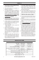
TROUBLESHOOTING Problem Possible Cause Corrective Action When ignitor button is 1. Ignitor electrode is posi- 1. Replace electrode. pressed in, there is no tioned wrong. Ignitor elecspark at ODS/pilot trode is broken. 2. Ignitor electrode is not con- 2. Replace ignitor cable nected to ignitor cable. 3. Ignitor cable is pinched or 3. Free ignitor cable if pinched wet. by any metal or tubing. Keep ignitor cable dry. 4 Broken ignitor cable. 4. Replace ignitor cable. 5. Bad piezo ignitor. 5.
TROUBLESHOOTING Problem Possible Cause Corrective Action Burner(s) does not light 1. Burner orifice is clogged. after ODS/pilot is lit 1. Clean burner orifice (see Care and Maintenance, page 24) or replace burner orifice. 2. Burner orifice diameter is too 2. Replace burner orifice. small. 3. Inlet gas pressure is too low. 3. Contact local gas supplier. Delayed ignition of 1. Manifold pressure is too low. 1. Contact local gas supplier. burner(s). 2. Burner orifice is clogged. 2.
TROUBLESHOOTING Problem Possible Cause Corrective Action Heater produces a click- 1. Metal is expanding while 1. This is common with most ing/ticking noise just after heating or contracting while heaters. If noise is excesburner is lit or shut off. cooling. sive, contact qualified service technician. White powder residue 1. When heated, the vapors 1. Turn heater off when using forming within burner from furniture polish, wax, furniture polish, wax, carpet box or on adjacent walls carpet cleaners, etc.
PARTS MODEL FDF300R 9 1 5 6 2 4 10 8 32 www.factorybuysdirect.
PARTS MODEL FDF300R This list contains replaceable parts for your heater. When ordering replacement parts, follow the instructions listed under Replacement Parts, page 34 of this manual.
REPLACEMENT PARTS Note: Use only original replacement parts. This will protect your warranty coverage for parts replaced under warranty. PARTS UNDER WARRANTY Contact authorized dealers of this product. If they can’t supply original replacement parts, call Customer Service toll free at 1-855-607-6557 for referral information.
ACCESSORIES Purchase these heater accessories from your local dealer. If they can not supply these accessories, contact Factory Buys Direct at 1-855-607-6557 for information. EQUIPMENT SHUTOFF VALVE For all models. Equipment shutoff valve with 1/2" NPT tap. OPTIONAL FAN KIT Optional fan kit part FIB100. The fan has 3 settings ON/OFF/Auto. 200253-01F www.factorybuysdirect.
WARRANTY KEEP THIS WARRANTY Model ________________________________ Serial No. _____________________________ Date Purchased ________________________ Keep receipt for warranty verification. REGISTER YOUR PRODUCT AT WWW.FACTORYBUYSDIRECT.