
BC1 and BC4X Evaporator Coil Installation Manual
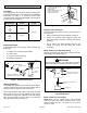
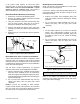
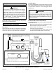
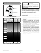
Table Of Contents

0674398-00 / 507792-01B Issue 1835 Page 5 of 8
If the system match requires an HFC-410A check/
expansion valve on the liquid line connection, the xed
orice device must be removed BEFORE a check/
expansion valve is installed. BC4X coils include a
factory-installed HFC-410A check/expansion valve.
BC1P Fixed Orice Removal (if necessary)
1. Remove the coil access and plumbing panels.
2. Remove any shipping clamps that secure the liquid
line and distributor assembly.
3. Using two wrenches, disconnect the liquid line stub
from the orice housing. Take care not to twist or
damage the distributor tubes during this process.
4. Remove and discard the existing orice, valve stem
assembly (if present) and Teon ring as illustrated in
Figure 4.
5. Retain brass nut to be used later with the liquid line
assembly.
O-RING
REMOVE AND DISCARD
WHITE TEFLON SEAL
STRAINER
DISTRIBUTOR
TUBES
LIQUID LINE
STUB
ORIFICE HOUSING
(REMOVE ORIFICE
FROM INSIDE OF
HOUSING)
Figure 4. Typical Fixed Orice Removal
BC1P Expansion Valve / Liquid Line Installation
Some system matches for the BC1P coil require a check/
expansion valve. The expansion valve must be installed
external to the indoor coil cabinet. Refer to the instructions
provided with the expansion valve kit for proper installation
of the valve and sensing bulb.
See the BC1P Product Specication for approved
expansion valve match-ups and application information.
1. After the expansion valve, equalizer line and sensing
bulb have been installed per the kit instructions,
braze the properly sized refrigerant piping into place.
Carefully follow brazing guidelines and use wet rags to
prevent heat damage.
2. Do not remove the water-saturated rags from the
cabinet and piping until the piping has cooled
completely.
NOTE: To prevent any possibility of water damage,
properly insulate all parts of the expansion valve assembly
that may sweat due to temperature differences between
the valve and its surrounding ambient temperatures.
BC4X Liquid Line Connection
BC4X coils include a factory-installed HFC-410A check/
expansion valve metering device.
Connect the properly sized eld-provided liquid line to
the liquid line stub as shown in Figure 5 using one of the
following procedures:
1. Position the properly sized refrigerant piping and
make the brazed connection following the brazing
guidelines.
2. Do not remove the water-saturated rags from the
cabinet and piping until the piping has cooled
completely.
OR
1. Cut the copper liquid line on a vertical or horizontal
section. Use a eld-provided coupling to join the
properly sized eld-provided refrigerant piping and
the liquid line stub on the coil. Follow the brazing
guidelines.
2. Do not remove the water-saturated rags from the
cabinet and piping until the piping has cooled
completely.
COIL LIQUID LINE
UNBRAZE AT FITTING
CUT TWO INCHES UP
CUT TWO INCHES OUT
COUPLING
SWEDGED CONNECTION
or
NOTE - Use the coupling at either of the two cut connections.
REMOVE AND DISCARD
VALVE STEM ASSEMBLY
(IF PRESENT)
Figure 5. BC4X Liquid Line Connections
Leak Testing, Evacuating and Charging
Refer to the outdoor unit instruction for leak testing,
evacuating and charging procedures. Always leak check
entire system before charging.