
Long Lineset Instructions


Page 1
APPLICATION AND DESIGN GUIDELINES
Refrigerant Piping
DESIGN AND FABRICATION GUIDELINES
Corp. 9351−L9
Revised May 16, 2013
TABLE OF CONTENTS
Introduction 1......................................
Piping Limits 1.....................................
Recommended Components 3.......................
Liquid Line Quick Select 3...........................
Vapor Line Quick Select 6...........................
Long Line Requirements 6..........................
Fundamentals and Theory 7........................
Line Sizing in Detail 9..............................
System Control 21.................................
System Operation 23..............................
Appendix A 24.....................................
Appendix B — XC25 / XP25 Line Set Requirements 33.
Glossary 34.......................................
Introduction
The piping design of any air conditioning system will affect
the performance, reliability, and applied cost of that system.
The design of refrigerant piping systems involves capacity
and efficiency, reliability, oil management, refrigerant
charge, sound level, liquid refrigerant control, modulation
effectiveness and cost. Therefore it is essential that the
installing contractor understand the effect of piping and be
able to make intelligent decisions in order to do the best job
possible on the installation. This material below will clearly
explain the basic effects on system performance of the
piping design.
In most typical installations with lines less than 50 feet, the
line sizes will match up to the connections on the outdoor
unit. However, with installations involving long line sets or
elevation differences between the outdoor unit and the
indoor unit, the piping must be sized carefully. System
performance may be improved even in a typical installation
by optimizing pipe sizes.
IMPORTANT !
The intent of this manual is to represent generally
accepted safe engineering practices. Specifications
and limits outlined in this manual are subject to
change. System design should conform to all codes,
laws and regulations applying at the site at the time
of installation. Additional documents that should be
followed include The Safety Code for Mechanical
Refrigeration and the Code for Refrigeration Piping,
both available from ASHRAE. In addition, the
procedures and limits outlined in this manual do not
supersede local, state or national codes under any
circumstances.
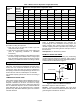
Piping Limits
All expansion valves (TXV) listed in the following tables can
be used in either air conditioner or heat pump systems.
These TXVs incorporate a check valve for heat pump
system applications.
Table 1. Indoor HFC-410A —TXV
Unit Size Catalog Number
2-Ton Y0498
3-Ton Y0499
4-Ton Y0500
5-Ton Y0501
6-Ton Y0502
Table 2. Indoor HCFC-22 —TXV
Unit Size Catalog Number
2-Ton Y0512
3-Ton Y0513
4-Ton Y0514
5-Ton Y0515
6-Ton Y0516
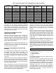
COOLING SYSTEM
HFC-410A
S Total equivalent length = 240 feet (Piping and all
fittings, etc).
NOTE — Length is general guide. Lengths may be more or
less, depending on remaining system design factors.
S Maximum linear (actual) length = 200 feet.
S Maximum linear liquid lift = 60 feet.
NOTE —- Maximum lifts are dependent on total length,
number of elbows, etc that contribute to total pressure drop.
S Maximum length vapor riser = 125 feet.
S Up to 50 linear feet: use rated line sizes listed in unit
specifications or installation instructions.