
Long Lineset Instructions


Page 16
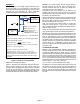
10 TON
CONDENSING
UNIT
10 TON
EVAPORATOR
53 FEET
40 FEET
FILTER/DRIER
3 FEET
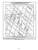
Given: 10−Ton Evaporator
Find: Liquid Line Size
Solution: Pressure drop cannot exceed 35
psi.
Tubing Size: 3/4 inch copper for 10−ton
system
Two 90º long radius elbows @ 3/4 inch O.D. = 1.25 foot equivalent
feet each.
Total equivalent length = linear length + equivalent length of fittings.
Total equivalent length = 98.5 feet.
Total friction losses =
1.6 psi
100 feet
x 98.5 feet = 1.57 psi.
Total pressure drop = Total friction losses + lift losses + filter/drier.
Filter drop = 1 psi (by manufacturer)
Lift losses = 40 feet x ½ psi per foot = 20 psi.
Total pressure drop – 20 psi + 1 psi + 1.57 psi = 22.57 psi.
Answer: ¾ inch O. D. copper tubing can be used. Pressure loss
does not exceed maximum allowable pressure drop (6ºF to 7ºF
subcooling will be available at the expansion valve and velocity is
acceptable.
10−Ton Condensing unit
With 10ºF subcooling at 125ºF
Length of line = 96 feet.
Figure 9. Liquid Line Sizing Example (Alternative)
SIZING SUCTION AND VAPOR LINES
The purpose of the suction line is the return of refrigerant
vapor and oil from the evaporator to the compressor. The
sizing of vertical risers is extremely important. Movement of
oil droplets up the inner surface of the tubing is dependent
on the mass velocity of the gas at the wall surface.
The larger the pipe the greater the velocity required at the
center of the pipe to maintain a given velocity at the wall
surface.
Suction line design is critical. The design must minimize
pressure loss to achieve maximum unit efficiency and yet
provide adequate oil return to the compressor under all
conditions.
Because oil separates from the refrigerant in the
evaporator, the suction velocity must be adequate to sweep
the oil along. Horizontal suction lines require a minimum of
800 fpm velocity for oil entrainment. Suction risers require
1200 fpm minimum and preferably 1500 fpm regardless of
the length of the riser.
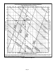
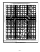
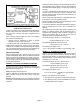
Figure 6 illustrates the relationship between suction line
sizing, pressure drop per 100 feet, velocity and cooling
tonnage. This chart is used to determine suction line
pressure drop which can then be used to determine suction
line capacity loss. This chart can also be used to determine
suction line velocity to assure oil return to the compressor.
Vertical lift does not significantly affect pressure drop.
However, systems will lose approximately 1% capacity for
every pound of pressure drop due to friction in the suction
line. This 1% factor is used to estimate the capacity loss of
refrigerant lines. To use the 1% factor, first you must use
figure 6 to estimate the pressure drop in the total equivalent
length of the lines you choose.
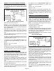
The Engineering Handbook capacity ratings of OEM split
system equipment show the capacity when matched with a
particular indoor coil and 25 feet. of refrigerant line. These
capacity ratings have the loss for a 25 feet. refrigerant line
already deducted. When you use this manual to estimate
the capacity loss due to friction, you must calculate the
pressure drop of the entire refrigerant line then subtract the
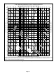
pressure drop of a 25 feet. line. See figure 10. Remember,
the objective is to hold refrigerant line capacity loss to a
minimum and maintain velocity for adequate oil return.
Figure 10. How to Find Capacity Loss
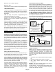
CONSIDERATIONS
When an evaporator is located above or on the same level
as the condensing unit, the suction line must rise to the top
of the evaporator. See figure 11. This helps prevent liquid
from migrating to the compressor during the off cycle. Traps
should also be installed at the bottom of all vertical risers.
In air conditioning systems, horizontal suction lines should
be level or slightly sloped toward the condensing unit. In air
conditioning and heat pump systems, pipe must avoid dips
or low spots that can collect oil. For this reason, hard copper
should be used, especially on long horizontal runs.