
Long Lineset Instructions


Page 21
The capacity lost in the total equivalent length of the
refrigerant line (using figures 6 and 10) = 1% x (3.34 –
0.825) x 120,000.
Btuh lost = 0.01 x (2.515) x 120,000
Btuh lost = 3018
Capacity loss for the line selected is approximately 2.5%.
Two Stage Applications
Many two stage applications will require a reduction in
suction riser size to maintain adequate velocity for oil return
at low stage. For example, a 5-ton two stage system will
normally use a 1-1/8 inch suction line (figure 6). A suction
riser in this system may be reduced to 7/8 inch pipe size
while the horizontal runs may use 1-1/8 inch pipe size.
Figure 6 shows the tradeoffs that will result from downsizing
the riser. The disadvantage is that the riser will exceed
3000 fpm when operating at full capacity (potential for
sound transmission). In addition, the pressure drop in the
smaller line will result in significantly greater pressure drop
(capacity loss). The advantage is that the smaller line will
guarantee sufficient velocity for oil return when operating at
reduced capacity.
If, by reducing the riser pipe size, the pressure drop
(capacity loss) becomes unacceptable, the system must be
designed with double suction risers.
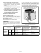
Accumulators
Accumulators have to pipe in between the reversing valve
and compressor on heat pumps, which usually do not have
room, especially in the under 5-ton units. Accumulator
sizing should be based on total system charge. A good rule
of thumb is to select an accumulator that can accommodate
2/3 of the total system charge.
Accumulators are not normally required on cooling only
systems with a non bleed TXV and crankcase heater.
Suction line size may be increased to minimize pressure
drop, provided that velocities are adequate. Liquid line
sizes should never be increased or decreased. Larger
liquid lines will add unnecessary charge to the system.
If liquid refrigerant is allowed to flood through an air
conditioning system and return to the compressor before
being evaporated, it may cause damage to the compressor
due to liquid slugging, loss of oil from the crankcase, or
bearing washout. To protect against this condition on
systems vulnerable to liquid damage, a suction
accumulator may be necessary.
Flooding typically can occur on heat pumps at the time the
cycle is switched between heating and cooling, reversal
before and after defrost, and during low ambient heating
operation. Flooding can also occur during normal pressure
equalization at system shut off, especially in systems with
large refrigerant charges. This is true for both heat pumps
and air conditioners.
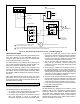
The accumulator's function is to intercept liquid refrigerant
before it can reach the compressor crankcase. It should be
located in the compressor suction line between the
evaporator and the compressor, and must have provisions
for a positive return of oil to the crankcase so that oil does
not become trapped in the accumulator. The liquid
refrigerant and oil must be metered back to the compressor
at a controlled rate to avoid damage to the compressor.
The actual refrigerant holding capacity needed for a suction
accumulator is governed by the requirements of the
particular application, and should be selected to hold the
maximum liquid refrigerant flood back anticipated.
One of the most critical areas of heat pump application is
the proper control of liquid refrigerant under low ambient
heating conditions. System design must maintain a delicate
balance between sufficient flooding to adequately cool the
compressor, while avoiding excessive flooding which
would adversely affect lubrication. When coil defrost is
required, the compressor is exposed to sudden surges of
liquid that can create extreme stresses in the compressor.
The accumulator can act as a reservoir for refrigerant
during the heating cycle when system imbalance or an
overcharge from field service result in excessive liquid
refrigerant in the system, storing the refrigerant until
needed and feeding it back to the compressor at an
acceptable rate.
Major movements of refrigerant take place at the initiation
and termination of a defrost cycle, and while it is not
necessary or even desirable to stop this movement, it is
essential that the rate at which the liquid refrigerant is fed
back to the compressor be controlled. Again the
accumulator can effectively maintain the crankcase
temperature at acceptable limits.
System Control
To operate at rated capacity and efficiency, all air
conditioning and heat pump systems must be properly
charged. Most equipment manufactured in recent years
depends on subcooling to attain rated capacity and
efficiency. See definition of subcooling in glossary of terms.
A unit can operate at what appears to be normal pressure
and temperature, and if the refrigerant charge does not
provide the proper subcooling for the application, as much
as 8 to 10% of its capacity can be lost without any reduction
in power consumption.
Some OEM equipment is designed to operate at peak
efficiency with less than 10F subcooling. Yet, if the
refrigerant incurs much restriction, such as that
experienced in vertical lift, less subcooling may not be
adequate and a loss of capacity will be experienced.
OEM equipment is designed so the refrigerant charge may
be adjusted in order to obtain 10-12F subcooling on
HCFC-22 units, 6-8F subcooling on HFC-410A units.
Many charging methods are available (charts, superheat,
approach, sight glass) but none of these methods will
assure you of a solid column of liquid at the expansion
valve. A favorite of the service technician has been the sight
glass. It will show that a solid column of liquid is present, but
it will not provide information regarding subcooling. A
common problem with a sight glass in a long line system is
that flash gas can form after the sight glass and before the
expansion valve. The sight glass should not be used to
determine proper system charge.