
Long Lineset Instructions


Page 6
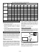
Table 7. BTUH Loss For Equivalent Length (HFC-410A)
Nominal
Tons
Tubing
Outside
Diameter
(Inches)
BTUH Loss For Equivalent Length (HFC-410A)
25' 50' 75' 100' 125' 150' 175' 200'
2
5/8 -100 -275 -460 -667 -846 -1014 -1268 -1487
3/4 0 -77 -169 -277 -384 -478 -602 -726
7/8 46 0 -57 -130 -196 -265 -360 -487
3
3/4 -89 -270 -452 -652 -839 -1071 -1354 -1564
7/8 0 -93 -167 -274 -407 -563 -742 -953
1 1/8 52 13 -11 -74 -188 -318 -441 -611
4
3/4 -208 -575 -918 -1356 -1613 -2026 -2429 -2824
7/8 0 -168 -320 -528 -726 -896 -1162 -1348
1 1/8 114 80 19 -58 -148 -266 -391 -537
5
7/8 -221 -598 -948 -1305 -1716 -2063 -2438 -2844
1 1/8 0 -109 -239 -398 -565 -741 -925 -1106
1 3/8 52 -33 -133 -239 -339 -478 -572 -775
Vapor Line Quick Select
Table 2 should be used to size the vapor line. Follow this
procedure for sizing the vapor line:
1. Find your unit on the left side of table 2 (for both
HCFC-22 and HFC-410A)
2. Start with the rated vapor line size on the outdoor unit
(refer to engineering handbook or installation
instructions)
3. You may consider increasing or decreasing the vapor
line size if a larger size is listed in table 2. Larger vapor
lines will reduce pressure drop and improve system
efficiency. For details see section Line Sizing in Detail.
Long Line Requirements
For systems with the outdoor unit 5-50 feet above the
indoor unit, one trap must be installed at the bottom of the
suction riser. For suction lifts between 50 and 100 feet
(cooling only units; vapor lifts over 50 feet not allowed on
heat pump), install a second trap halfway up the riser. For
suction lifts over 100 feet, install traps at 1/3 intervals.
For variable capacity systems see section Line Sizing in
Detail.
COMBINATION VAPOR LINES
Vapor risers must be sized to ensure adequate velocity for
oil return. In general, piping can be designed to ensure
adequate velocities for oil return even with two stage
systems. A good way to do this is to reduce the vapor riser
size. A combination vapor line can be constructed with the
larger diameter pipe in the horizontal runs to minimize
pressure drop, and smaller diameter pipe in the vertical to
increase velocities.
NOTE — Maximum vapor riser = 125 feet
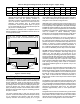
Table 5 simplifies vapor/suction line selection by
incorporating all of the calculations involving vapor line
sizing, pressure drop, velocity range and tonnage. To
calculate capacity loss due to pressure drop in the vapor
line refer to the section Sizing Suction and Vapor Lines in
this document.
Assumptions: 2-4 elbows every 50 feet
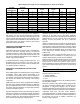
EXAMPLE: VAPOR LINE SIZING
Given: 7-1/2 ton HCFC-22 A/C cooling only condensing
unit with evaporator lower than condenser, with 112 feet of
piping. The piping includes 20 feet of vertical lift and 92 feet
of horizontal run as illustrated in figure 2.
INDOOR COIL
SUCTION RISER
90 FT.
2 FT.
40 FT.
OIL TRAP
Figure 2. Indoor Coil Below Condenser
Find: Select vapor line size from table 5.
Solution: 1-3/8 inch outside diameter line is the rated
suction line size. It is listed on table 5 because it will provide
good refrigerant velocities for oil return.