
Long Lineset Instructions


Page 9
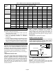
Table 10. Refrigerant Charge (Pounds) in 100 feet of Type L Copper Tubing
Line
Size
3/8” 1/2” 5/8” 5/8” 3/4” 3/4” 7/8” 7/8” 1-1/8” 1-3/8” 1-5/8” 2-1/8
Liquid Liquid Liquid Suction Liquid Suction Liquid Suction Suction Suction Suction Suction
HCFC−22 3.8 7.0 11.3 0.3 16.8 0.4 23.4 0.6 1.0 1.6 2.2 3.9
HFC−410A 3.1 5.8 9.2 0.4 13.8 0.6 19.2 0.8 1.3 2.0 2.9 5.0
2. Pressure drop in the liquid line produces no significant
capacity loss as long as 100% liquid is delivered to the
expansion valve and the pressure available is
adequate to produce the required flow. Pressure drop
due to lift must be added to the friction losses to
determine total pressure drop. At normal liquid
temperatures, HCFC-22 pressure drops 0.5 psi per
foot of vertical liquid lift. HFC-410A pressure drops 0.43
psi per foot of vertical liquid lift.
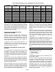
One contributor to pressure loss in refrigerant lines is
elbows and fittings. Figure 3 illustrates how lines can be run
to avoid pressure losses.
ÄÄÄÄÄÄÄÄÄÄÄÄÄÄÄ
ÄÄÄÄÄÄÄÄÄÄÄÄÄÄÄ
ÄÄÄÄÄÄÄÄÄÄÄÄÄÄÄ
ÄÄÄÄÄÄÄÄÄÄÄÄÄÄÄ
ÄÄÄÄÄÄÄÄÄÄÄÄÄÄÄ
ÄÄÄÄÄÄÄÄÄÄÄÄÄÄÄ
ÄÄ
ÄÄ
ÄÄ
ÄÄ
ÄÄ
ÄÄ
ÄÄ
ÄÄ
ÄÄÄÄÄÄÄÄÄÄÄÄÄÄÄ
ÄÄÄÄÄÄÄÄÄÄÄÄÄÄÄ
ÄÄÄÄÄÄÄÄÄÄÄÄÄÄÄ
ÄÄÄÄÄÄÄÄÄÄÄÄÄÄÄ
ÄÄÄÄÄÄÄÄÄÄÄÄÄÄÄ
ÄÄ
ÄÄ
ÄÄ
ÄÄ
ÄÄ
ÄÄ
ELBOWS AND FITTINGS PRODUCE PRESSURE DROP.
CAREFULLY ROUTE LINES TO AVOID OBSTACLES IN PATH OF
LINES.
ACCEPTABLE HIGHER PRESSURE DROPS.
RECOMMENDED LOWER PRESSURE DROPS.
Figure 3. Pressure Drops
Line Sizing in Detail
The first step in the design of a piping system is to layout the
entire system (i.e. relative location of the condensing unit
and the evaporator, length of each segment of the piping
system, length of suction risers and liquid risers etc). Start
by making a sketch of the system including lengths of pipe,
number of elbows, tees, valves, and any other irregular
piping and fittings needed. This information will be used to
determine total equivalent length for calculating pressure
drop due to friction.
The same methods apply to both A/C and heat pump
systems. A suction line sized to produce adequate velocity
for oil entrainment and pressure drop with minimum
capacity reduction will function properly as a hot gas
discharge line during a heating cycle. Also, if there is a
vertical difference in height between the outdoor and indoor
units, there is always a vapor and liquid lift to consider in
sizing due to the reversal of refrigerant flow.
OEM split system condensing units and heat pumps (four
tons and under) match with line sets of varying lengths of up
to 50 feet (linear). These applications offer quick and simple
installations that are trouble free if the line sets are properly
installed. On split commercial applications and residential
installations beyond 50 feet, special design considerations
must be followed to assure satisfactory system
performance. An improperly designed system could result
in a serious loss of capacity or even compressor failure.
The purpose of the liquid line is to convey a full column of
100% liquid from the condenser to the metering device at
the evaporator without flashing. The amount of liquid line
pressure drop which can be tolerated is dependent on the
number of degrees of liquid subcooling leaving the
condenser and the saturated condensing temperature. If
the condensing temperature and subcooling are known,
the maximum allowable pressure drop can be calculated.
All OEM equipment is designed so that the charge may be
adjusted to provide adequate subcooling leaving the
outdoor unit. This will allow a 30 pound drop in the
HCFC-22 liquid line (including pressure drop due to friction
loss and vertical lift) and 35 psi in the HFC-410A liquid line.
Refrigerant charge may be added to increase subcooling to
overcome pressure drop due to liquid lift. Heat pumps
require special consideration when adding charge because
both cooling and heating modes must be considered.
Consult the installation guide for the specific unit you are
working with.
A major cause of compressor failure is liquid slugging. Due
to the additional refrigerant required to fill the lines, the
likelihood of slugging is greatly increased with lines over 50
feet in length. It is desirable to use the smallest liquid line
that will not result in refrigerant flashing due to pressure
drop. Table 10 shows that each incremental increase in
liquid line size results in a 40 to 50 percent increase in liquid
to fill the line.
The liquid line must not directly contact the vapor line. If the
refrigerant line plan results in a pressure drop of 20 psi or
more, the liquid line should be insulated in all places where
it passes through an environment (such as an attic) which
experiences temperatures higher than the subcooled
refrigerant (approximately 105F to 115F liquid at 95F
ambient).
Refrigeration lines must not be buried in the ground unless
they are insulated and waterproofed. Un-insulated copper
lines buried in wet soil or under concrete can cause serious
capacity loss and erratic operation as well as early failure
due to corrosion. See Appendix for more information.