
Long Lineset Instructions

Page 23
YRGW
TO A/H FAN
TO A/H HEAT
THERMOSTAT
CONTROL RELAY
PUMP DOWN RELAY
LIQUID LINE SOLENOID VALVE 24 VAC
C/U Y1 TO
COMPRESSOR
CONTACTOR
LOW PRESSURE
SWITCH
A/H TRANSFORMER
L
N
1
2
1
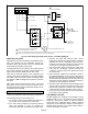
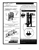
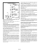
IF NECESSARY REPLACE A/H TRANSFORMER
WITH ONE OF ADEQUATE VA CAPACITY.
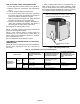
INSTALL LOW PRESSURE CONTROL ON SECTION LINE AT CONDENSING UNIT. TO AVOID OIL MIGRATION INTO THE CONTROL BODY,
MOUNT THE LOW PRESSURE CONTROL ABOVE THE HEIGHT OF THE COMPRESSOR.
2
Figure 19. Non-Recycling Pump Down Control - Field Wiring Diagram
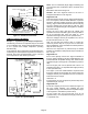
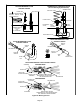
VIBRATION AND NOISE
Regardless of how well a condensing unit is isolated, some
noise and vibration will be transmitted through the
refrigerant piping. But this effect can be minimized with
proper design and support of the piping.
On residential units a coil of tubing in the condensing unit
may provide adequate protection against vibration. On
larger commercial unit, flexible hose is often used.
Noise can be caused by gas flow, fans, compressor, and
mounting. Sometimes a combination of gas flow and piping
will create a resonant frequency which can amplify sound
and vibration. OEM has designed the systems to minimize
this effect.
When piping passes through walls or floors, ensure that
piping does not touch any structural members and is
properly supported by hangers. Otherwise vibration can be
transmitted into the building.
System Operation
Cooling-only applications with reciprocating compressor
The following sequence refers to figure 19:
1. On a call for cooling, the thermostat energizes the Y
circuit which in turn energizes the control relay.
2. The control relay energizes the liquid line solenoid
valve and prepares a circuit to energize the
pump-down relay when the low pressure switch closes.
3. Opening the liquid line solenoid valve causes
refrigerant to flow from the higher pressure condenser
and liquid line into the evaporator and suction line.
Pressure in the suction line quickly rises to the 55 psig
cut-in pressure closing the low pressure switch.
4. The low pressure switch energizes the pump down
relay and the compressor contactor starting the
condenser. The pump down relay seals itself around
the control relay.
5. When cooling is satisfied, the thermostat Y circuit is
de-energized dropping out the control relay and the
liquid line solenoid valve. The compressor continues to
operate pumping refrigerant from the evaporator and
suction line into the condenser and liquid line which is
sealed by the closed liquid line solenoid.
6. When the suction line pressure drops to 25 psig the low
pressure switch opens de-energizing the pump down
relay and the compressor contactor. The compressor
cannot operate until there is another call for cooling.
7. Lower cut-in and cut-out pressures may be required for
low ambient cooling operation.
LOW AMBIENT COOLING
All OEM equipment is designed for low ambient cooling
operation down to 50F. Low ambient cooling operation
below 50F requires the addition of OEM low ambient
control kits and a crankcase heater. Cooling operation
below 30F requires OEM low ambient control kit plus a
variable speed controller on the outdoor fan(s). Table 11
refers to line lengths over 50 feet.