
Long Lineset Instructions

Page 28
From figure 4, 5/8 inch outside diameter. liquid line with 7
tons capacity has 2.3 psi drop per 100 feet. When we
multiply 2.3/100 by 11 equivalent feet, we see that the total
friction loss is 0.25 psi.
Now, we must add the pressure drop for vertical lift.
HCFC-22 pressure drop is 1/2 psi per foot of vertical lift.
When multiplied by 10 feet vertical lift we find that pressure
drop due to lift = five psi.
When the components of pressure drop are added together
we find that the total pressure drop in this 5/8 inch line =
5.25 psi.
Segment D to E
S D to E has a capacity of five tons. Select from figure 4
a ½ inch outside diameter. line (smallest line with
acceptable velocity). Then determine the equivalent
length of the segment to calculate the pressure drop.
S Forty feet of pipe, plus one tee (branch side of tee at 2.0
equivalent feet each) = 42 equivalent feet length.
S From figure 4, 1/2 inch outside diameter. liquid line with
five tons capacity has 4.6 psi drop per 100 feet. When
we multiply 4.6/100 by 42 equivalent feet, we see that
the total friction loss is 1.93 psi.
S Vertical lift = 0.
S In this segment, the only component of pressure drop
is the equivalent length; 1.93 psi.
Segment D to F
S D to F has a capacity of two tons. Select from figure 4
a 3/8 inch outside diameter. line (smallest line with
acceptable velocity). Then determine the equivalent
length of the segment to calculate the pressure drop.
S Twelve feet of pipe, plus one 90 elbow (0.8 equivalent
feet each) = 12.8 equivalent feet length (round up to 13
equivalent feet).
S From figure 4, 3/8 inch outside diameter. liquid line with
2 tons capacity has four psi drop per 100 feet. When we
multiply 4/100 by 13 equivalent feet, we see that the
total friction loss is 0.52 psi.
S Now, we must add the pressure drop for vertical lift.
HCFC-22 pressure drop is ½ psi per foot of vertical lift.
When multiplied by 10 feet vertical lift we find that
pressure drop due to lift = five psi.
S When the components of pressure drop are added
together we find that the total pressure drop in this 3/8
inch line = 5.52 psi.
Putting the Segments Together
Next, we must determine if the line sizes we selected will
result in satisfactory pressure drop between the
condensing unit and each evaporator. To do this we simply
add the total pressure drop of each line segment between
the condensing unit and each evaporator. Remember the
total pressure drop between the condensing unit and
evaporator should be less than 30 psi.
S Total pressure drop A to C = A to B plus B to C.
S Total pressure drop = 6 + 0.33 = 6.33 (Acceptable).
S Total pressure drop A to E = A to B plus B to D plus B
to C.
S Total pressure drop = 6 + 5.25 + 1.93 = 6.33
(Acceptable).
S Total pressure drop A to F = A to B plus B to D plus D
to F.
S Total pressure drop = 6 + 5.25 + 5.52 = 16.77
(Acceptable).
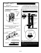
Complex Suction Line Sizing
When a single condenser is connected to more than one
evaporator, there are additional rules which must be
followed when designing the refrigerant piping. These rules
apply to separate coils in separate air handlers as well as to
split coils in a single air handler.
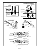
First, the total evaporator load must at least equal the
condensing unit capacity. Next, when evaporators in
different levels are connected to a single main, the suction
line from each coil must rise to the top of that coil before
joining the main. Finally, all connections to a suction main
must loop over and enter the top of the main to avoid the
gravity draining of oil into the suction risers during off
cycles.
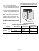
Figure 23. Vapor Piping Indoor Coils above and
below Main
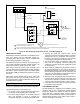
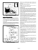
Example 2 – Suction Sizing with Multiple Evaporators
On systems with multiple evaporators operating
simultaneously connected to a single condensing unit,
suction lines are sized similar to the method used for sizing
liquid lines. Each line segment is sized based on the tons of
refrigerant flowing in the segment.
In this example, all the evaporators are located above the
condensing unit so that none of the evaporators experience
the effects of suction lift. The system is equipped with a 2
ton, 5 ton and 3 ton evaporator in order from top to bottom.
Given: 10 ton condensing unit with three evaporators,
higher than condenser, operating simultaneously.