
Long Lineset Instructions


Page 31
Putting the Segments Together
Next, we must determine if the line sizes we selected will
result in satisfactory pressure drop between the
condensing unit and each evaporator. To do this we simply
add the total pressure drop of each line segment between
the condensing unit and each evaporator. Then we convert
the pressure drop into a capacity loss for each coil.
Remember, there is approximately 1% loss in capacity for
each pound of pressure lost to the line.
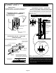
2-ton evaporator:
S Total pressure drop A to F = A to B plus B to D plus D
to F.
S If 5/8 inch outside diameter. line is used from D to F:
S Total pressure drop = 0.99 + 0.6 + 2.53 = 4.12
S If ¾ inch outside diameter. line is used from D to F:
S Total pressure drop = 0.99 + 0.6 + 0.87 = 2.46
S 1% capacity loss for each pound pressure drop
S 0.01 x 2.46 x 24,000 = 590 Btuh lost if ¾ inch line is
used.
S 0.01x 4.12 x 24,000 = 989 Btuh lost if 5/8 inch line is
used.
3-ton evaporator:
S Total pressure drop A to C = A to B plus B to C.
S Total pressure drop = 0.99 + 1.11 = 2.1 psi
S 1% capacity loss for each pound pressure drop
S 0.01 x 2.1 x 36,000 Btuh = 756 Btuh lost.
5-ton evaporator:
S Total pressure drop A to E = A to B plus B to D plus D
to E.
S Total pressure drop = 0.99 + 0.6 + 1.55 = 3.14 psi
S 1% capacity loss for each pound pressure drop
S 0.01 x 3.14 x 60,000 Btuh = 1884 Btuh lost.
When deciding which line should be used from D to F,
compare the capacity loss to the capacity required. Use the
larger line size only if the additional capacity is needed to
satisfy the job requirements.
If the line segments to these evaporators were significantly
longer resulting in excessive capacity loss, larger suction
lines could be selected as long as satisfactory velocities for
oil entrainment were maintained.
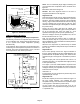
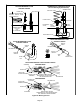
DISTRIBUTOR
ASSEMBLY
EXPANSION
VALVE
(LB−85663A−E Shown)
TEFLON WASHER
(SUPPLIED WITH KIT)
CONNECT
LIQUID LINE
SET HERE
SENSING
BULB
(ATTACH TO
SUCTION LINE)
EQUALIZER CONNECTION
(SECURE TO EQUALIZER
PORT ON SUCTION LINE)
TEFLON WASHER
(SUPPLIED WITH KIT)
STUBBED
END OF VALVE
Figure 26. Typical Residential Applications