
Long Lineset Instructions

Page 7
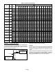
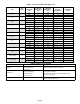
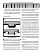
Table 8. Equivalent Length in Feet of Straight Pipe for Valves and Fittings
LINE SIZE
(OUTSIDE
DIAMETER) INCH
SOLENOID
/GLOBAL GLOBE
VALVE
ANGLE VALVE
90º LONG* RADIUS
ELBOW
45º LONG* RADIUS
ELBOW
TEE LINE TEE BRANCH
3/8 7 4 0.8 0.3 0.5 1.5
1/2 9 5 0.9 0.4 0.6 2.0
5/8 12 6 1.0 0.5 0.8 2.5
3/4 14 7 1.3 0.6 0.9 3.0
7/8 15 8 1.5 0.7 1.0 3.5
1-1/8 22 12 1.8 0.9 1.5 4.5
1-3/8 28 15 2.4 1.2 1.8 6.0
1-5/8 35 17 2.8 1.4 2.0 7.0
2-1/8 45 22 3.9 1.8 3.0 10
2-5/8 51 26 4.6 2.2 3.5 12
* Long radius elbow. Multiply factor by 1.5 for short radius elbow equivalent length.
Table 5 shows that a larger suction line size is available for
this system. You may consider increasing the horizontal
vapor line size to 1-5/8”. This larger horizontal vapor line will
reduce pressure drop and improve system efficiency. The
larger vapor size is not advisable for the vertical vapor rise.
Consult the section Line Sizing in Detail for exact velocity
and pressure drop calculations.
ADDITIONAL REQUIREMENTS FOR AIR
CONDITIONER SYSTEMS
Applications with less than 50 linear feet of refrigerant line
may use fixed RFC metering devices on approved
matchups as listed in engineering handbook. Plans with
less than 50 linear feet of line and less than 20 feet of lift
may also use OEM pre-fabricated line sets if available as
listed in engineering handbook.
In applications where cooling operation below 50 F is
anticipated and an economizer is not being used, low
ambient (head pressure) controls must be installed. See
Low ambient section in Appendix.
ADDITIONAL REQUIREMENTS FOR HEAT PUMP
SYSTEMS
Some OEM equipment is equipped with a factory installed
accumulator. Never add a second accumulator. If an
accumulator is not supplied and one must be added, the
accumulator must be properly sized and must be located in
the suction line between the reversing valve and the
compressor.
OEM heat pump units are factory equipped with a liquid line
filter drier. Never install a liquid line filter drier in addition to
factory installed driers due to risk of excess pressure drop
and risk of improper installation. A bi-flow drier should be
used with heat pump systems.
Special consideration must be given to heat pump systems
when there is a difference in elevation between the outdoor
and indoor units. Due to the reversal of refrigerant flow from
heating to cooling cycle, there is always a liquid and suction
lift to consider when sizing the refrigerant lines.
Maximum liquid lift should not exceed 50 linear feet for
HCFC-22, or 60 linear feet for HFC-410A. Additional
pressure drop due to friction will result in total pressure drop
approaching the 30 psi maximum that could produce
flashing in HCFC-22 systems (35 psi in HFC-410A
systems).
Likewise, maximum suction lift must not exceed 50 feet for
HCFC-22 or 60 feet for HFC-410A due to limitations placed
on the liquid line. (When refrigerant flow is reversed, a liquid
drop will become a liquid lift). The vapor line must be sized
as a suction riser with adequate velocity for oil return if there
is any difference in elevation between the indoor and
outdoor units.
In applications where cooling operation below 50 F is
anticipated and an economizer is not being used, low
ambient (head pressure) controls must be installed.
Solenoid valves are uni-directional devices. Since solenoid
valves are uni-directional, they are seldom used on heat
pump systems. If used, they require a check valve to
bypass refrigerant around the solenoid during the heating
cycle. Never install a pump-down cycle on a heat pump
system.
Fundamentals and Theory
The three prime considerations when designing a
refrigerant piping scheme are:
1. System reliability
2. System performance
3. Cost
The desirable characteristics of any air conditioning system
are described in table 8:
There are a number of ways that the piping system design
can affect compressor reliability. Many compressors are
susceptible to refrigerant slugging and oil dilution.
Oversized liquid lines increase the amount of refrigerant in
a system which creates the potential for these problems.
Undersized liquid lines can also create problems.
Undersized liquid lines can cause refrigerant to flash before
the expansion device. The result of a starved evaporator in
this situation can be loss of capacity, evaporator coil
frosting, or high superheat.