
Long Lineset Instructions

Page 8
Suction lines and vapor lines must also be carefully sized.
Oversized suction lines may result in refrigerant velocities
being too low to return oil to the compressor. Undersized
suction lines reduce capacity, cause increased refrigerant
velocity sound and cause high superheat.
Long refrigerant lines have to be carefully planned.
Excessive line length can reduce system capacity and lead
to reliability problems.
The largest penalty for pressure drop is in the suction line.
An acceptable pressure drop in the suction line is 3 PSI with
HCFC-22 and 5 PSI with HFC-410A. In very long runs
pressure drop can exceed these values. However, the most
important function of the suction line is oil return, so in very
long runs the higher pressure drop may be necessary.
The most important function of the liquid line is to deliver a
solid column of 100% liquid refrigerant to the expansion
device. Liquid lines are kept small to reduce the amount of
system charge. As long as the pressure drop in the liquid
line does not cause the refrigerant to flash, the liquid line
diameter can be kept small. Adequate subcooling
guarantees that the expansion device will see 100% liquid
refrigerant.
Any pressure drop in the liquid line due to vertical lift must
also be taken into consideration. This pressure drop should
be added to the friction loss in the liquid line to figure the
total pressure drop of the liquid line. The maximum
acceptable pressure drop in the liquid line is 30 PSI for
HCFC-22 and 35 psi for HFC-410A.
In order to keep installed cost down, the contractor should
use the smallest possible tubing that will yield acceptable
friction losses in the system.
OIL MANAGEMENT
Small amounts of oil from the compressor are constantly
being circulating with the refrigerant throughout the system.
This oil must be returned to the compressor for proper
lubrication of bearings and contact surfaces. Suction and
vapor lines must be sized carefully to eliminate oil
management problems.
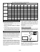
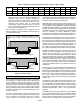
For systems with the outdoor unit 5-50 feet above the
indoor unit, one trap must be installed at the bottom of the
suction riser. For suction lifts between 50 and 100 feet
(cooling only units; vapor lifts over 50 feet not allowed on
heat pump), install a second trap halfway up the riser. For
suction lifts over 100 feet, install traps at 1/3 intervals.
Oil return is a major consideration since some oil is
continually being circulated with the refrigerant. Oil must be
returned to the compressor by entrainment with the
refrigerant vapor. Minimum velocity must be approximately
800 feet per minute (fpm) in horizontal runs, and
approximately1200 fpm in vertical suction risers.
HCFC-22
Lines over 50 feet and with suction line 7/8 inch outside
diameter or smaller, add three ounces of oil for each 10 feet
of line over 50 feet. For systems with 1-1/8 inch outside
diameter and larger suction lines, add four ounces of oil for
each 10 feet of line above 50 feet. Consult the OEM
engineering handbook or installation instructions for proper
oil type.
HFC-410A
Recommend adding oil to system based on the amount of
refrigerant charge in the system. No need to add oil in
systems with 20 pounds of refrigerant or less. For systems
over 20 pounds - add one ounce of every five pounds of
refrigerant.
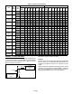
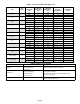
EQUIVALENT LENGTH
Each valve, fitting, and bend contributes to friction pressure
drop because of the interruption of smooth flow. Because it
can be difficult to calculate the pressure drop of each fitting
it is more useful to use equate the pressure drop to an
equivalent length of straight tubing for each fitting. This
makes it easier to add up the entire length of line, including
fittings and valves, as an equivalent length of straight pipe.
Pressure drop and line sizing tables are set up on the basis
of pressure drop per 100 feet of straight pipe. The
equivalent length of copper tubing for commonly used
valves and fittings can be found in table 8.
PRESSURE DROP
Refrigerant piping involves complex relationships in the
flow of refrigerant and oil. The flow of refrigerant involves
the interaction of many factors, including velocity, pressure,
friction, density, viscosity and the work required to force the
flow. The nature of refrigerant flow is well understood
because of practical experience. Any flow through a pipe
leads to pressure drop or friction losses. The smaller the
pipe the higher the pressure drop. Table NO TAG generally
explains the effect of pressure drop in a refrigerant piping
system.
Table 9. Location of Pressure Drop
Location of
Pressure Drop
Affect On System Performance
Suction Line
Significantly reduces system ca
pacity and efficiency
Hot Gas Lines
Reduces system capacity and ef
ficiency
Liquid Line
No penalty on system perfor
mance as long as there is a solid
column of liquid at the expansion
device
Pressure drop is important from a performance standpoint.
The following general statements point out the effects of
pressure drop in the various components of the
refrigeration piping system.
1. Pressure drop in the suction line reduces capacity and
increases power consumption. For air conditioning
systems, a one pound drop in the suction line reduces
capacity approximately one percent. A suction line
pressure drop of up to thee psi for HCFC-22 (five psi for
HFC-410A) is generally acceptable.