
Long Lineset Instructions

Page 17
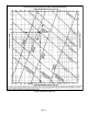
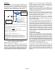
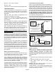
Figure 11. Suction Line Piping Indoor Coil above
Outdoor Unit or Same Level
To aid in the return of oil, a trap should be installed at the
bottom of any suction riser (remember, a heat pump vapor
line can act as a suction riser when refrigerant flow is
reversed).
When selecting suction/vapor line sizes, the following
points must be remembered:
1. Velocity must be maintained in order to provide
adequate oil return to the compressor.
2. Capacity loss must be held within the job requirements.
Field installed components, such as suction line driers,
mufflers, etc. contribute to both pressure drop and capacity
loss. The resultant pressure drop must be considered (see
manufacturer's data for pressure drop information).
SIZING PROCEDURE
Before selecting pipe size, make a sketch of the layout
complete with fittings, driers, valves etc. Measure the linear
length of each line and determine the number of ells, tees,
valves, driers etc. Add equivalent length of fittings (table 4)
to linear length of pipe to get total equivalent length used in
determining friction loss.
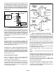
EXAMPLE 1: SUCTION LINE SIZING PROCEDURE
Given: Five ton HCFC-22 (60,000 Btuh) condensing unit
on same level with condenser, with 65 feet of piping and
eight elbows (as in figure 11).
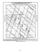
Find: Select tube size from figure 6.
Figure 6 illustrates the relationship between suction line
sizing, pressure drop per 100 feet, velocity range and
tonnage.
Solution: Enter figure 6 from left (tons capacity) and extend
to the right to the smallest tube size with velocity less than
3000 fpm.
Suction line velocity should not exceed 3000 fpm in order to
avoid possible noise complaints. This rule may be slightly
exceeded when added velocity is required to entrain oil
vertically.
1-1/8 inch outside diameter line with 2.8 psi per 100 feet
pressure drop and 1950 fpm velocity is selected. Now
calculate pressure drop due to friction loss to determine if
this is a good selection.
65 feet of pipe, plus eight elbows (1.8 equivalent feet each,
from table 8) = 79.4 feet equivalent length.
When we multiply 2.8/100 by 79.4 equivalent feet, we see
that the total friction loss is 2.22 psi.
1-1/8 inch line appears to meet the requirements in figure 6.
Find the capacity loss in 1-1/8 in. line to determine net
capacity.
Air Conditioning and Heat Pump system capacities are
based on matched systems with 25 equivalent feet of
refrigerant line operating at ARI conditions. As figure 10
shows, the pressure drop in 25 feet of line must be
subtracted from the total equivalent length.
The pressure drop in 25 feet of 1-1/8 inch line is:
2.8/100 multiplied by 25 = 0.7 psi
The additional pressure drop for the line is:
2.22 psi minus 0.7 psi = 1.52 psi
The capacity loss (figure 10) is:
0.01 x 1.52 x 60,000 = 912 Btuh or approximately 1.5%.
EXAMPLE 2: ALTERNATIVE PIPE SIZE
Suppose 7/8 inch outside diameter. line with a pressure
drop of 12 psi per 100 feet had been selected. 65 feet of
pipe, plus eight elbows (1.5 equivalent feet each) = 77 feet
equivalent length. The total friction drop would be 12/100
multiplied by 77 = 9.24 psi.
The pressure drop in 25 feet of 7/8 inch line is:
12/100 multiplied by 25 = 3 psi
The additional pressure drop for the line is:
9.24 psi minus 3 psi = 6.24 psi
The capacity loss (figure 10) is:
0.01 x 6.24 x 60,000 = 3744 Btuh or approximately
6.24%.
This is a poor selection for two reasons:
1. The high velocity may cause excess auction line noise.
2. The capacity loss may not be acceptable if the system
is designed with close tolerance.