
BC1 and BC4X Evaporator Coil Installation Manual
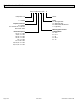
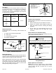
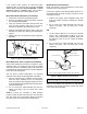
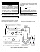
Table Of Contents

0674398-00 / 507792-01B Issue 1835 Page 7 of 8
Blower Speed Selection
LEFT-HAND AIR
DISCHARGE (TOP VIEW)
TEST HOLES
AIR FLOW
Figure 7. Static Pressure Test
Cabinet
Vol: CFM
Drop: in. w.g.
Model Width in. Dry Wet
18/24A
14.5 600 .11 .17
14.5 800 .18 .25
18/24B
17.5 600 .11 .17
17.5 800 .18 .25
24A 14.5 800 .16 .18
24B 17.5 800 .16 .18
30A 14.5 1000 .18 .20
30B 17.5 1000 .18 .20
30/36A
14.5 1000 .19 .21
14.5 1200 .27 .30
30/36B
17.5 1000 .13 .16
17.5 1200 .17 .21
30/36C
21 1000 .13 .16
21 1200 .17 .21
36A 14.5 1200 .27 .30
36B 17.5 1200 .17 .21
48B
17.5 1400 .23 .24
17.5 1600 .30 .31
48C
21 1400 .13 .16
21 1600 .16 .20
49C 21 1600 .17 .22
50/60C 21 1600 .23 .29
60C 21 2000 .29 .34
60D 24.5 2000 .21 .27
Table 2. Air Volume / Static Pressure Drop Across Coil
Take care when drilling test holes into the furnace ange
and the duct. Drill holes away from refrigerant piping.
Test holes should be drilled where specied in order to
avoid unit damage.
CAUTION
Proper air volume must be provided over the evaporator
coil. Select a blower motor speed tap that will provide 400
± 50 CFM per 12,000 Btuh of cooling capacity (wet coil). A
static pressure reading must be taken to see if the pressure
drop falls within the proper range. See Table 2.
To ensure accuracy, air must be read from below the coil
and above the coil. See Figure 7 for an example to obtain
an accurate reading.
1. Drill one 5/16” air test hole into the delta plate between
the coil slabs.
2. Drill one 5/16” air test hole into the duct above the top
of the coil.
3. Connect the instrument for static pressure
measurement hoses to the air entering side of coil.
Insert the hoses so that 1/4” extends inside the duct or
end seal. Seal around holes with Permagum®.
4. Turn on electrical power to the furnace and set the
thermostat to initiate a cooling demand.
5. Table 2 lists air volumes and equivalent static pressure
readings for these units. Observe the static pressure
reading. If the reading is below the required air
volume, increase the blower speed; if the reading is
above the required air volume, decrease the blower
speed. Refer to the furnace wiring diagram for blower
speed settings.
6. When the required static pressure readings are
obtained, remove the test hose lines and insert snap
hole plugs into test holes.