
Long Lineset Instructions

Page 10
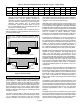
Systems with buried refrigerant lines can experience
significant or total capacity loss if allowed to transmit heat to
the surroundings. In addition, buried lines are susceptible
to corrosion which can shorten the life of the system. For
this reason, buried lines must rest inside a sealed,
watertight, thermally insulated conduit. The lines must not
contact the soil for any reason and the conduit must be
designed so it cannot collect and retain water.
In all installations with lines over 50 feet, use only hard
copper refrigeration tubing (clean and dry). Soft copper is
prone to sagging in long horizontal runs. Elbows, Tees,
Couplings and other joints should be made of wrought
copper and elbows should be long radius. For leak free
joints, properly clean tubing and fittings and use a brazing
material with a minimum 5% silver content sil-phos. To
prevent copper oxides from forming inside copper tubing it
is necessary to bleed dry nitrogen through the tubing during
the soldering process.
WARNING
Danger of fire. Bleeding the refrigerant
charge from only the high side may result
in the low side shell and suction tubing
being pressurized. Application of a
brazing torch while pressurized may
result in ignition of the refrigerant and oil
mixture - check the high and low
pressures before unbrazing.
WARNING
When using a high pressure gas such as
dry nitrogen to pressurize a refrigeration
or air conditioning system, use a regulator
that can control the pressure down to 1 or
2 psig (6.9 to 13.8 kPa).
The primary purpose of the liquid line is to ensure a solid
column of liquid refrigerant at the expansion valve.
Refrigerant velocity is not a consideration in the liquid line,
since the oil will mix completely with the liquid refrigerant.
Pressure loss is a consideration in the liquid line. If the
pressure of the liquid refrigerant drops below its saturation
temperature, some of the liquid will flash into vapor to cool
the remaining liquid refrigerant to the new saturation
temperature. This can occur in a liquid line if the pressure
drops enough due to either friction loss or vertical lift.
Flash gas must be avoided in the liquid line. The only way to
know for sure that a solid column of liquid is present at the
expansion device is to check subcooling. A sight glass may
be full of liquid, but bubbles can still form past the sight
glass. Flash gas at the expansion device can erode
damage a TXV, can cause noise, and may cause starvation
of the evaporator coil. The section on System Control
explains how to charge a unit using subcooling.
SIZING LIQUID LINES
Two factors must be considered when sizing liquid lines –
pressure drop in the lines and pressure drop across the
expansion device and distributor. The maximum pressure
drop line the lines must be determined to ensure adequate
subcooling at the expansion device. See examples below.
EXAMPLE 1: MAXIMUM ALLOWABLE PRESSURE
DROP
A mid efficiency HCFC-22 unit operating at 10F
subcooling and 125F (280 psi) condensing temperature,
find the maximum allowable pressure drop in the liquid line.
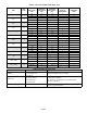
Refer to the pressure/ temperature chart (table 15) in the
appendix. 125 F condensing temperature minus 10F
subcooling equals 115F sub-cooled liquid temperature
(245 psi - this is the pressure below which subcooled liquid
will begin to form flash gas). 280 psi condensing pressure
minus 245 psi subcooled pressure equals 35 psi.
Pressure drop in the liquid lines is not detrimental to system
performance provided that 100% liquid is available entering
the expansion device. For the most part, the generation of
flash gas will be determined by the amount of pressure drop
in the liquid line. To calculate total pressure drop in liquid
lines, the following must be determined then added
together:
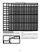
1. Pressure drop due to friction in pipe (figure 4) fittings
and field installed accessories such as a drier, solenoid
valve or other devices (table 4). The pressure drop due
to friction is usually smaller than pressure drop due to
lift but must be considered. The pressure drop ratings
of field installed devices is usually supplied by the
manufacturer of the device and should be used if
available.
2. Pressure drop due to vertical liquid lift (0.5 pound per
foot for HCFC-22 and 0.43 pound per foot for
HFC-410A) is usually large and may be a limiting factor
in the ultimate design of the system.
Next, the pressure entering the expansion device must be
sufficient to produce the required flow through the
expansion device. A pressure drop of 100 psi for HCFC-22
(175 psi for HFC-410A) across the expansion valve and
distributor is necessary to produce full refrigerant flow at
rated capacity. Therefore, it is necessary for liquid
refrigerant (free of flash gas) to be delivered to the
expansion valve at a minimum of 175 psi for HCFC-22 or
340 psi for HFC-410A.
EXAMPLE 2: MAXIMUM ALLOWABLE PRESSURE
DROP
A high efficiency HFC-410A unit operating at 6F
subcooling and 115F (390 psi) condensing temperature,
find the maximum allowable pressure drop in the liquid line.
Refer to the pressure/ temperature chart in the appendix.
115 F condensing temperature minus 6F subcooling
equals 109F sub-cooled liquid temperature (360 psi – this
is the pressure below which subcooled liquid will begin to
form flash gas), 390 psi condensing pressure minus 360 psi
subcooled pressure equals 30 psi.