
Long Lineset Instructions


Page 24
OEM low ambient kits are available for all OEM (expansion
valve equipped) units. These kits may need to be installed
and may need to be supplemented with field installed
equipment when applied to systems with long refrigerant
lines. Field installed equipment may include any or all of the
following: solenoid valve installed in the liquid line at the
evaporator, pump-down controls, accumulator, additional
crankcase heaters or capacity unloading.
Factory supplied low ambient kits may include low ambient
thermostat, low pressure switch, relays or any combination
of the above. The variable speed controller, freezestat, and
crankcase heater are available through OEM Dealer
Service Centers.
The operation of each kit can vary somewhat between
cooling and heat pump units. Refer to the low ambient kit for
specific information.
Generally, the low ambient kits are wired to accomplish the
following: Low pressure switches are installed to sense
head pressure and cycle the condenser fan. The fan is
cycled in order to keep head pressure high during low
ambient operation. Variable speed controllers may require
ball bearing fan motors for proper operation at low speed.
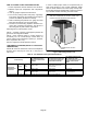
If low ambient operation is required and the outdoor unit is
exposed to high prevailing winds, a permanent wind barrier
should be constructed to protect the outdoor coil. In cooling
operation, high prevailing winds can significantly reduce
head pressure. In heat pumps, high prevailing winds can
reduce the effectiveness of the defrost cycle. Use the
minimum installation clearances (provided in Engineering
Handbook) as a guide when constructing a wind barrier.
Wind barriers should extend vertically to the height of the
coil.
Appendix A
HFC-410A REFRIGERANT
The phase out of HCFC-22 refrigerant is currently
underway in the U.S. The official deadline for all equipment
manufacturers to change over to more environmentally
friendly refrigerants is 2010. Aftermarket HCFC-22 will be
available until 2020. HFC-410A is quickly becoming the
refrigerant of choice to replace HCFC-22 in residential and
light commercial air conditioning equipment.
HFC-410A is a near-azeotropic mixture of R-32 and R-125
refrigerants. HFC-410A operates at 50% higher pressure
than HCFC-22. Due to the higher pressure, OEM has
upgraded system components in HFC-410A systems.
HFC-410A must not be used to retrofit existing HCFC-22
equipment. HFC-410A can only be used in equipment
designed for HFC-410A.
Operating pressure points are different for HCFC-22 and
HFC-410A:
Table 12. Head Pressures
50F Evaporator
/ 115F Condens
er
HCFC-22 HFC-410A
Suction Pressure 84 psig 143 psig
Head Pressure 243 psig 390 psig
Table 13. Recommended Hose Pressure Capabilities.
High-pressure Hoses
Minimum 700-psig service
pressure rating
High-pressure manifold
gauge sets
700 psig on the high side
Minimum 180 psig low side
550-psig low-sided retard
High-pressure recovery
units
See manufacturer's
recommendations.
High-pressure recovery
tanks
The recovery cylinder ser
vice pressure rating must
be 400 psig, DOT 4BA400,
or DOT 4BW400.
Proper joint brazing and maintenance becomes even more
critical with HFC-410A. When servicing HFC-410A system,
the contractor must make sure to use components
specifically designed for HFC-410A.
Special service equipment required for working with
HFC-410A includes:
It is recommended that charging with HFC-410A be done in
the liquid phase. Use a commercial-type metering device in
the manifold hose. Charge into the suction line with the
compressor running. See OEM installation instructions for
more details on proper charging procedures.
HFC-410A systems use POE oils. POE oils absorb
moisture very quickly. Keep oil containers tightly closed.
Expose the system to atmosphere as little as possible.
The filter driers uses with HFC-410A systems are designed
with higher working pressures and desiccant materials that
are compatible with POE oils and HFC refrigerants.
Change the filter drier anytime the system is opened to the
atmosphere.
HFC-410A systems manufactured by OEM are either
expansion valve systems or fixed orifice. Proper refrigerant
charge for TXV systems should be checked by the
approach method. Proper refrigerant charge for orifice
systems should be checked by the subcooling method.
The maximum liquid line pressure drop in HFC-410A
systems is 35 PSI, which equates to six degrees of
subcooling. The recommended suction line pressure drop
is five PSI, which equates to two degrees of saturated
suction temperature.