
Long Lineset Instructions

Page 3
b) If indoor unit does not have a factory installed TXV,
or factory installed TXV needs replacing due to
system match, up or the factory TXV is not capable
of maintaining low enough superheats, use table 1
for ordering the correct TXV for specific size indoor
unit. All of these are indoor non-bleed adjustable
thermostat check expansion valves. Superheat
adjustment procedures can be found in the TXV kit
instructions.
S If not factory provided, high and low pressure
switches are recommended. Low pressure switch
bypass switch will be required on units that do not
have provision to ignore the switch when unit is
operating in ambient temperatures below 15°F.
S If not factory provided, a liquid line filter drier is
required.
S For HFC-410A recommend adding oil to system
based on the amount of refrigerant charge in the
system. No need to add oil in systems with 20
pounds of refrigerant or less. For systems over 20
pounds - add one ounce of every five pounds of
refrigerant.
HCFC-22
S Total equivalent length = 180 feet (Piping and all
fittings, etc).
NOTE — Length is general guide. Lengths may be more or
less, depending on remaining system design factors.
S Maximum linear (actual) length = 150 feet.
S Maximum linear liquid lift = 50 feet.
NOTE — Maximum lifts are dependent on total length,
number of elbows, etc that contribute to total pressure drop
plus when the outdoor unit is above the indoor unit.
S Maximum length vapor riser = 50 feet.
S Up to 50 linear feet: use rated line sizes listed in unit
specifications or installation instructions.
S If 51 to 150 linear feet: Crankcase heater required,
non-bleed port TXV (see TXV note below) required.
S If 81 - 200 linear feet: Crankcase heater and non-bleed
port TXV (see TXV note) required.
S Over 150 linear feet: not recommended.
TXV NOTE:
a) Indoor Factory Installed non-bleed, non-adjustable
TXV can be used on the system if it can maintain
superheat lower than 25°F at outdoor unit service
valve. (Superheat is critical to compressor operating
conditions)
b) If indoor unit does not have a factory installed TXV,
or factory installed TXV needs replacing due to
system match, up or the factory TXV is not capable
of maintaining low enough superheats, use table 2
for ordering the correct TXV for specific size indoor
unit. All of these are indoor non-bleed adjustable
thermostat check expansion valves. Superheat
adjustment procedures can be found in the TXV kit
instructions.
S If not factory provided, high and low pressure
switches are recommended. Low pressure switch
bypass switch will be required on units that do not
have provision to ignore the switch when unit is
operating in ambient temperatures below 15°F.
S If not factory provided, a liquid line filter drier is
required.
S For HFC-22 systems with suction lines over 50 feet
with lines that are 7/8” or smaller, add three ounces
of oil every 10 feet of line over 50 feet. For systems
with 1-1/8” and larger suction lines, add four ounces
of oil every 10 feet of line over 50 feet.
Recommend Components
PRESSURE TAPS
Should be installed at the inlet and outlets of indoor coils to
allow field measurement of saturated pressures for
calculating superheats and sub-cooling values.
ANTI-SHORT PROTECTION
Systems should have anti-short cycle.
S ON - usually four minutes.
S Timed OFF - usually five minutes and timer
NOTE — A number of electronic thermostats contain these
features)
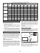
OPTIONAL SIGHT GLASS
A glass window type device placed in a liquid line and used
for visual inspection of the liquid. It can also be used to
determine the point at which all gas bubbles are removed
from liquid line. A sight glass is not a good indicator of
sub-cooling and cannot be used to determine charge.
Optional Sight Glass Catalog Numbers are listed in table 3.
Table 3. Sight Glass Catalog Numbers
Liquid Line Size
Catalog Number
3/8” 57K19
1/2” 19B62
5/8” 19B63
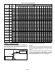
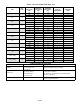
Liquid Line Quick Select
Table 4 should be used to size the liquid line when there is a
liquid lift. Follow this procedure for sizing the liquid line:
1. Find your unit on the left side of table 4.
2. Start with the rated liquid line size on the outdoor unit
(refer to engineering handbook or installation
instructions)
3. Read over to the linear length shown at the top of table
4.
4. Does maximum elevation meet your needs? If yes, use
this size liquid line.
5. If not, consider the larger line size shown in table 4.
For variable capacity systems see section Line Sizing in
Detail.
Table 4 simplifies liquid line selection by incorporating all of
the calculations involving liquid line sizing, pressure drop,
velocity range and tonnage.