
Long Lineset Instructions


Page 33
Appendix B — XC25 / XP25 Line Set Requirements
The XC/XP25 is a variable capacity cooling and heat pump
system utilizing variable speed compressor technology.
With the variable speed compressor and variable pumping
capacity, additional consideration must be given to
refrigerant piping sizing and application. The guidelines
below are to be used exclusively for the XC/XP25 systems.
COOLING AND HEAT PUMP SYSTEMS (HFC410A)
S Total equivalent length equals 180 feet (piping and all
fittings included).
NOTE — Length is general guide. Lengths may be more or
less, depending on remaining system design factors.
S Maximum linear (actual) length = 150 feet.
S Maximum linear liquid lift = 60 feet.
NOTE — Maximum lifts are dependent on total length,
number of elbows, etc. that contribute to total pressure
drop.
S Maximum length vapor riser equals 60 feet.
S Vertical vapor riser must be sized to the vapor riser
listed in the table 16.
S Up to 50 Linear Feet: use rated line sizes listed in unit
specifications or installation instructions.
S Between 51 150 Linear Feet: Crankcase heater and
nonbleed port TXV factory installed. No additional
components required. Use tables 16 and 17 to
determine the correct liquid and vapor line sizes.
S Over 150 Linear Feet: not recommended.
S Additional oil is not required for systems with line
lengths up to 150 feet except for the XP25-048 and
XP35-060, which will required 2 ounces of oil for every
10 feet beyond 100 feet.
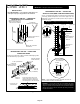
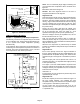
SUCTION TRAPS
For systems with the outdoor unit 5 60 feet above the
indoor unit, one trap must be installed at the bottom of the
suction riser.
Table 16. XC/XP25 Piping Guidelines
Model
Maximum Total
Equivalent Length (ft)
Maximum Linear
(actual) Length (ft)
Maximum Vapor
Riser (ft)
Maximum
Linear Liquid
Lift (ft)
Preferred
Vapor Line
Sizes for
Horizontal
Runs
Required Vapor
Riser Size
024 180 150 60 60 7/8” 5/8”
036 180 150 60 60 7/8” 3/4”
048 180 150 60 60 7/8” 7/8”
060 180 150 60 60 7/8” 7/8”
Table 17. Liquid Line Diameter Selection Table
Unit
Line Size
Total Linear Length (feet)
25 50 75 100 125 150
024
5/16” 25 50 55 48 40 33
Max. Elevation
(ft)
3/8” 25 50 60 60 60 60
036
3/8” 25 50 60 56 51 45
1/2” 25 50 60 60 60 60
048
3/8” 25 50 50 41 31 22
1/2” 25 50 60 60 60 60
060
3/8” 25 50 36 22 8 NR
1/2” 25 50 60 60 60 59
Note Shaded rows indicate rated liquid line size
1. Find your unit on the left side of the table.
2. Start with the rated liquid line size (shaded row) on the outdoor unit
3. Select the actual Total Linear Length of your system shown at the top of the table.
4. The elevation listed in the table is the maximum allowed for the liquid line listed.
5. Select or consider the larger liquid line size shown in the table if the elevation does not meet your requirements.