
Air Handler Heat Coil Installation Instructions

Page 3
Electrical Connections
WARNING
Electric shock hazard! - Disconnect all power
supplies before servicing.
Replace all parts and panels before
operating.
Failure to do so can result in death or
electrical shock.
IMPORTANT
USE COPPER CONDUCTORS ONLY
NOTE – Refer to the nameplate on the air handler unit
for minimum circuit ampacity and maximum overcurrent
protection size.
The air handler units are provided with openings to be
used with 1-1/2 inch trade size (1-31/32 inch diameter)
conduit.
If you want a single point power supply, refer to the name-
plate on the single point power supply accessory for min-
imum circuit ampacity and maximum overcurrent protec-
tion size. Select the proper supply circuit conductors in
accordance with tables 310-16 and 310-17 in the National
Electric Code, ANSI/NFPA No. 70 or tables 1 through 4 in
the Canadian Electric Code, Part I, CSA Standard C22.1.
Refer to gure 13 for typical low voltage eld wiring for
air handler/condensing unit and heat pump applications.
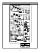
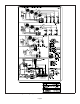
Figure 8 is a diagram of the air handler connections and
the heater high-voltage wiring.
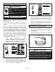
1 - Make wiring connections as follows:
Heaters equipped with circuit breakers —
Connect eld power supply wiring to circuit
breaker(s). Figure 5 shows L1, L2 and ground
(GND) connections for a 2-breaker conguration.
ON
OFF
60
ON
OFF
60
L1
L2
CIRCUIT 1
L1
L2
CIRCUIT 2
GND
208/240 VOLT FIELD
SUPPLY WIRES
Field Supply
Ground Wires
FIGURE 5. Field Power Supply Wiring
Heaters equipped with terminal blocks — Con-
nect eld power supply wiring to terminal block(s).
Figure 6 shows L1, L2 and ground (GND) connec-
tion for a terminal block conguration.
L1
L2
GND
208/240 VOLT FIELD
SUPPLY WIRES
FIELD SUPPLY
GROUND WIRES
FIGURE 6. Terminal Block Connections
2 - Remove the interface harness from the air handler
unit and connect the 6-pin connector on the heater
assembly to the mating connector on the air handler
unit.
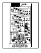
3 - For applications using a two-stage room thermostat
and/or an outdoor thermostat, connect wiring as
shown in gures 9 and 10.
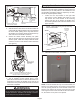
Circuit Breaker Cover Installation
1 - Remove any installed patch plates still present.
2 - Remove paper backing from the adhesive around
the perimeter of the back side of the circuit breaker
cover (gure 7).
3 - Position the breaker cover over the air handler
circuit breaker opening.
CIRCUIT BREAKER COVER
(BACKSIDE)
REMOVE PAPER COVERING
ADHESIVE BACK
FIGURE 7. Remove Paper Cover
IMPORTANT
Conrm air tight seal between breaker cover and air
handler access panel. Apply a thin silicone bead to the
adhesive back seat to ensure air tight seal.
Failure to seal circuit breaker cover will allow warm
moist air to be pulled into control panel which can create
condensation to form on the circuit breaker and other
electrical components within the control panel.