
Air Handler Heat Coil Installation Instructions


Page 2
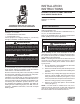
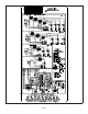
NO‐HEAT
SEAL PLATE
REMOVE SCREWS;
THEN REMOVE
NO-HEAT SEAL
PLATE
SEPARATE CONNECTOR;
DISCARD WIRE HARNESS
WIRE
HARNESS
REMOVE FASTENER SECURING WIRES
IF PRESENT
FIGURE 1. Prepare to Install Heat Element
5 - Slide the electric heat section into the air handler. Be
careful that the heating elements do not rub against
the sheet metal opening when they slide into the
air handler. The mounting holes should then line up
with holes in the air handler control box.
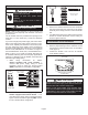
6 - Secure the electric heater assembly into place
with the screws that were removed from the heat
element panel. Install two eld-provided #8 SDST
screws in the front of the electric heater assembly
(see gure 2).
INSTALL SCREWS
REMOVED FROM
THE NO-HEAT
SEAL PLATE.
INSTALL 2 FIELD-PROVIDED SCREWS TO SECURE THE
FRONT OF THE HEATER CIRCUIT BREAKER ASSEMBLY TO
THE FRONT FLANGE OF THE AIR HANDLER.
FIGURE 2. Installing the Heat Element Assembly
7 - The air handler’s access panels have a cover
plate that is fastened with a screw and will need to be
positioned to t either one breaker or two, but do not
install the access panel until all electrical connections
have been completed.
WARNING
Foil face insulation must be cut to eliminate the possibility
for any frayed foil to come in contact with any main or low
voltage connections. Insulation must be kept a minimum
of 1/2" away from any electrical connection.
Changing Circuit Breaker Orientation
The air handler comes from the factory ready for hori-
zontal right hand discharge installation. Always rotate the
breaker so up is the ON position in all orientations. The
circuit breaker orientation change is required by UL 1995,
Article 26.18 (25 September 2005).
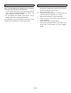
1 - Locate the one clip located on the right side
(see arrow) of each breaker (see gure 3). The
clip secures the circuit breaker to the mounting
bracket. Pull the clip to release the breaker from
the mounting bracket and rotate the breaker to the
proper postition.
CLIP
BREAKER(S)
MOUNTING
BRACKET
NOTE - There may be only one clip securing
each circuit breaker.
CIRCUIT
BREAKER
FIGURE 3. Circuit Breaker Clip
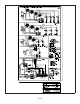
2 - Install the circuit breaker cover plate.
FIGURE 4. Circuit Breaker Cover Plate
NOTE – If electric heat kit has only one circuit breaker, the
breaker cover plate needs to be moved up and installed
over the opening without the circuit breaker. Fasten the
breaker cover plate to the access panel using the circled
hole in gure 4. If the electric heat kit has two circuit break-
ers, the breaker cover plate is not required.