
Comfort Aire GUH GDD LP Gas Conversion Installation Guide

507371-02 Issue 1706 Page 3 of 5
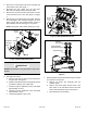
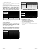
NOx Insert
Re-install
Screws
Figure 5. NOx Inserts
8. Re-install the manifold/valve assembly.
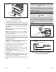
9. Thread provided brass tting to gas valve inlet until
hand tight. Using properly sized wrench, tighten tting
2 to 3 full turns being careful to position the side port to
allow clearance for the pressure switch and harness.
See Figure 6.
NOTE: Never use channel lock pliers or a pipe wrench
on the brass tting.
NOTE: Some installations may require the pressure
switch and tting assembly to be positioned differently
than shown in Figure 6.
10. Thread the gas supply to the brass tting until hand
tight. Using properly sized wrench to support brass
tting, tighten supply line into tting 2 to 3 full turns to
achieve leak free joint.
NOTE: Do not over tighten. (Maximum 3 full turns past
hand tight for ½” NPT per ASME B1.20.1-2013)
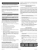
11. Thread pressure switch to brass tting 2 to 3 turns
past hand tight, then wire as shown in Figure 7.
12. Restore the electrical power to the unit.
13. Inspect all sides of assembly. Turn on gas supply.
Immediately check the entire tting surface and
assembly joints for gas leaks.
14. Afx nameplate conversion sticker next to unit
nameplate.
15. Complete the information required on the gas converter
sticker: date, name, and address. Afx sticker to the
exterior of the unit in a visible area.
16. Follow the steps given in the start-up and adjustment
section.
IMPORTANT
Carefully check all piping connection for gas leaks. DO
NOT use matches, candles, open ames or other means
of ignition to check for gas leaks. Use a soap solution or
other preferred means.
CAUTION
Some soaps used for leak detection are corrosive to
certain metals. Carefully rinse piping thoroughly after
leak test has been completed. Do not use matches,
candles, ame or other sources of ignition to check for
gas leaks.
Low Inlet Pressure
Switch
Brass Fitting
Figure 6. Gas Valve with Low Inlet Pressure Switch
GAS VALVE
NO
C
WHITE
ORANGE
LOW INLET
PRESSURE
SWITCH
BROWN
ORANGE
PROVIDED HARNESS WIRES
YELLOW
Figure 7. Low Inlet Pressure Switch Wiring
Point-to-Point Wiring Diagram