
Comfort Aire GUH GDD LP Gas Conversion Installation Guide

507371-02Issue 1706Page 4 of 5
Start-Up & Adjustment
BEFORE PLACING THE UNIT INTO OPERATION
Smell all around the appliance area for gas. Be sure to
smell next to the oor because LP/Propane gas is heavier
than air and will settle on the oor.
Use only your hand to move the gas control switch. Never
use tools. If the switch will not move by hand, do not try to
repair it. Force or attempted repair may result in a re or
explosion.
A - Placing the Unit into Operation
IMPORTANT
Follow the lighting instructions provided on the unit.
If lighting instructions are not available, refer to the
following section.
Units are equipped with a two-stage integrated ignition
system. The integrated ignition control automatically lights
the burners each time the thermostat calls for heat.
1. STOP! Read the safety information at the beginning
of this section.
2. Set the thermostat to its lowest setting.
3. Turn off all electrical power to the furnace.
4. Do not try to light the burners by hand.
5. Remove the unit access panel.
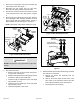
6. Move the switch on the gas valve to OFF. Do not force
the switch. See Figure 1.
7. Wait ve (5) minutes for any gas to clear out. If you
then smell gas, STOP! Immediately call your gas
supplier from a neighbor’s phone. Follow the gas
supplier’s instructions. If you do not smell gas, go to
the next step.
8. Move the switch on the gas valve to ON.
9. Replace the unit compartment access panel.
10. Turn on all electrical power to the unit.
11. Set the thermostat to desired setting.
12. If the furnace will not operate, see section E- “Turning
Gas Off to the Unit” and call the gas supplier.
Gas Pressure Measurement
A - Supply Pressure Measurement
An inlet pressure post located on the gas valve provides
access to the supply pressure. See Figure 1. Back out the
3/32 hex screw one turn, connect a piece of 5/16 tubing
and connect to a manometer to measure supply pressure.
Check the unit on high re. On multiple unit installations,
check the unit separately and with the other units operating.
See Table 1 for supply line pressure. Following the supply
pressure check, turn off unit, remove manometer and
tighten post hex screw.
B - Measuring & Adjusting the Manifold Pressure
A952 & 95G2 Models
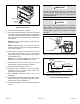
A manifold pressure post located on the gas valve provides
access to the manifold pressure. See Figure 1. Back out
the 3/32 hex screw one turn, connect a piece of 5/16
tubing and connect to a manometer to measure manifold
pressure. To correctly measure manifold pressure, the
differential pressure between the positive gas manifold
and the negative burner box must be considered. Furnace
should operate at least 5 minutes before checking manifold
pressure.
1. Connect the test gauge positive side “+“ to manifold
pressure tap on gas valve as noted above.
2. Tee into the gas valve regulator vent hose and connect
to test gauge negative “-”.
3. Ignite unit on low re and let run for 5 minutes to allow
for steady state conditions.
4. After allowing unit to stabilize for 5 minutes, record
low re manifold pressure and compare to value given
in Table 1. If necessary, make adjustment. Figure 1
shows location of low re adjustment screw.
5. Repeat on high re and compare to value given in
Table 1. If necessary, make adjustment. Figure 1
shows location of high re adjustment screw.
A802 & 80G2 Models
A manifold pressure post located on the gas valve provides
access to the manifold pressure. See Figure 1. Back out
the 3/32 hex screw one turn, connect a piece of 5/16
tubing and connect to a manometer to measure manifold
pressure.
1. Connect test gauge to manifold pressure post (Figure
1) on gas valve.
2. Ignite unit on low re and let run for 5 minutes to allow
for steady state conditions.
3. After allowing unit to stabilize for 5 minutes, record
manifold pressure and compare to value given in
Table 1.
4. If necessary, make adjustments. Figure 1 shows
location of high re and low re adjustment screws.
5. Repeat steps 2, 3 and 4 on high re. See values in
Table 1.
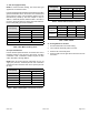
Manifold Pressure in w.g. Gas Line Pressure in w.g.
Low Fire High Fire Minimum Maximum
4.9 10.0 11.0 13.0
Table 1. Manifold and Gas Line Pressure