INSTALLATION INSTRUCTIONS BG801UHE Warm Air Gas Furnace Upflow / Horizontal Left and Right Air Discharge This manual must be left with the homeowner for future reference. This is a safety alert symbol and should never be ignored. When you see this symbol on labels or in manuals, be alert to the potential for personal injury or death. Table of Contents Unit Dimensions...........................................................2 BG801UHE Gas Furnace.............................................
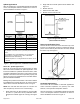
Unit Dimensions NOTE -C*20 size units installed in upflow applications that require air volumes of 1800 cfm (850 L/s or greater must have one of the following: 1 1. 2. 3. 4. 5. 25 (635) D Single side return air with transition, to accommodate 20 x 25 x 1 in. (508 x 635 x 25 mm) air filter. Single side return air with optional RAB Return Air Base Bottom return air. Return air from both sides. Bottom and one side return air. Top View Flue outlet may be horizontal but furnace must be vented vertically.
Clearances BG801UHE Gas Furnace The BG801UHE gas furnace is shipped ready for installation in the upflow or horizontal right position (for horizontal left position the combustion air pressure switch must be moved). The furnace is shipped with the bottom panel in place. The bottom panel must be removed if the unit is to be installed in horizontal or upflow applications with bottom return air. Adequate clearance must be made around the air openings into the vestibule area.
Heating Unit Installed Parallel to Air Handler Unit Heating Unit Installed Upstream of Cooling Unit Figure 1. When installed, this furnace must be electrically grounded according to local codes. In addition, in the United States, installation must conform with the current National Electric Code, ANSI/NFPA No. 70. The National Electric Code (ANSI/NFPA No.
In addition to the requirements outlined previously, the following general recommendations must be considered when installing one of these furnaces: • Place the furnace as close to the center of the air distribution system as possible. The furnace should also be located close to the chimney or vent termination point. • Do not install the furnace where drafts might blow directly into it. This could cause improper combustion.
for combustion if the structure does not provide enough air by infiltration. If the furnace is located in a building of tight construction with weather stripping and caulking around the windows and doors, follow the procedures in the air from outside section. Confined Space A confined space is an area with a volume less than 50 cubic feet (1.42 m3) per 1,000 Btu (.29 kW) per hour of the combined input rating of all appliances installed in that space.
Setting Equipment WARNING Do not install the furnace on its front or its back. Do not connect the return air ducts to the back of the furnace. Doing so will adversely affect the operation of the safety control devices, which could result in personal injury or death. The gas furnace can be installed as shipped in either the upflow position or the horizontal position. Select a location that allows for the required clearances that are listed on the unit nameplate.
Upflow Applications Allow for clearances to combustible materials as indicated on the unit nameplate. Minimum clearances for closet or alcove installations are shown in Figure 7. Type of Vent Connector Type C Type B1 Top 1 in. (25 mm) 1 in. (25 mm) *Front 2-1/4 in. (57 mm) 2-1/4 in. (57 mm) Back 0 0 Sides 0† 0 Vent 6 in. (152 mm) 1 in. (25 mm) Floor 0‡ 0‡ 2. Single side return air with optional return airbase. See Figure 12. 3. Bottom return air. 4. Return air from both sides.
This furnace may be installed in either an attic or a crawl space. Either suspend the furnace from roof rafters or floor joists, as shown in Figure 10, or install the furnace on a platform, as shown in Figure 13. Type of Vent Connector Type C Type B1 Top 0 0 *Front 2-1/4 in. (57 mm) 2-1/4 in. (57 mm) Back 0 0 Ends 2 in. (51 mm) 2 in. (51 mm) Vent 6 in. (152 mm) 1 in. (25 mm) Floor 0‡ 0‡ * Front clearance in alcove installation must be 24 in. (610 mm). Maintain a minimum of 24 in.
NOTE: Heavy gauge perforated sheet metal straps may be used to suspend the unit from roof rafters or ceiling joists. When straps are used to suspend the unit in this way, support must be provided for both the ends. The straps must not interfere with the plenum or exhaust piping installation. Cooling coils and supply and return air plenums must be supported separately.
When return air is drawn from a room, a negative pressure is created in the room. If a gas appliance is operating in a room with negative pressure, the flue products can be pulled back down the vent pipe and into the room. This reverse flow of the flue gas may result in incomplete combustion and the formation of carbon monoxide gas. This toxic gas might then be distributed throughout the house by the furnace duct system.
• Cut combustion air inducer tubing from 9” to 5” to avoid interference with inducer motor. • Cut combustion air inducer tubing from 9” to 7” to avoid interference with inducer motor. Figure 17. Upflow Position Right Side Vent Discharge • Disconnect pressure switch hose from barbed fitting on the pressure switch assembly. Remove pressure switch assembly (1 screw) and cut wire tie to free pressure switch wires.
WARNING Asphyxiation hazard. The exhaust vent for this furnace must be securely connected to the furnace flue transition at all times. Figure 21. Horizontal Right Position Side Vent Discharge These series units are classified as fan assisted Category I furnaces when vertically vented according to the latest edition of National Fuel Gas Code (NFPA 54 / ANSI Z223.1) in the USA.
A fan assisted furnace may be commonly vented into an existing lined masonry chimney if the following conditions are met: • The chimney is currently serving at least one drafthood equipped appliance. • The vent connectors and chimney are sized according to the provided venting tables. If type B1 double wall vent is used inside a chimney, no other appliance can be vented into the chimney. The outer wall of type B1 vent pipe must not be exposed to flue products.
1. Vent diameter recommendations and maximum allowable piping runs are found in the provided venting tables. 2. In no case should the vent or vent connector diameter be less than the diameter specified in the provided venting tables. 3. The minimum vent capacity determined by the sizing tables must be less than the low fire input rating and the maximum vent capacity must be greater than the high fire input rating. 4.
Capacity of Type B Double Wall Vents with Type B Double Wall Connectors Serving a Single Category I Appliance Height H (feet) 6 8 10 15 20 30 Lateral L (feet) Vent and Connector Diameter - D (inches) 3 inch 4 inch 5 inch 6 inch Appliance Input Rating in Thousands of Btu per Hour MIN MAX MIN MAX MIN MAX MIN MAX 0 0 78 0 152 0 251 0 375 2 13 51 18 97 27 157 32 232 4 21 49 30 94 39 153 50 227 6 25 46 36 91 47 149 59 223 0 0 84 0 165 0 276 0 415 2
Vent Connector Capacity Type B Double Wall Vents with Type B Double Wall Connectors Serving Two or More Category I Appliances Vent Height H (feet) Connector Rise R (feet) 6 8 10 15 20 30 Vent and Connector Diameter - D (inches) 3 inch 4 inch 5 inch 6 inch Appliance Input Rating in Thousands of Btu per Hour MIN MAX MIN MAX MIN MAX MIN MAX 1 22 37 35 66 46 106 58 164 2 23 41 37 75 48 121 60 183 3 24 44 38 81 49 132 62 199 1 22 40 35 72 49 114 64 176 2 2
Removal of the Furnace from Common Vent In the event that an existing furnace is removed from a venting system commonly run with separate gas appliances, the venting system is likely to be too large to properly vent the remaining attached appliances. Conduct the following test while each appliance is operating and the other appliances (which are not operating) remain connected to the common venting system.
Gas Pipe Capacity - FT³/HR (kL/HR) Nominal Iron Pipe Size inches (mm) Internal Diameter - inches (mm) Length of Pipe - feet (m) 10 (3.048) 20 (6.096) 30 (9.144) 1/2 (12.7) .622 (17.799) 175 (4.96) 120 (3.40) 97 (2.75) 82 (2.32) 73 (2.07) 66 (1.87) 61 (1.73) 57 (1.61) 53 (1.50) 50 (1.42) 3/4 (19.05) .824 (20.930) 360 (10.19) 250 (7.08) 200 (5.66) 170 (4.81) 151 (4.28) 138 (3.91) 125 (3.54) 118 (3.34) 110 (3.11) 103 (2.92) 1 (25.4) 1.049 (26.645) 680 (19.25) 465 (13.
3. The gas piping must not run in or through air ducts, clothes chutes, gas vents or chimneys, dumb waiters, or elevator shafts. 4. The piping should be sloped 1/4 inch (6.4 mm) per 15 feet (4.57 m) upward toward the meter from the furnace. The piping must be supported at proper intervals [every 8 to 10 feet (2.44 to 3.01 m)] with suitable hangers or straps. Install a drip leg in vertical pipe runs to the unit. 5. A 1/8” N.P.T.
connected to this terminal with the neutral leg of the circuit being connected to one of the provided neutral terminals. If a humidifier rated at greater than one amp is connected to this terminal, it is necessary to use an external relay. One 24V “H” 1/4” spade terminal is provided on the furnace control board. Any humidifier rated up to 0.5 amp can be connected to this terminal with the ground leg of the circuit connected to ground or the “C” terminal. See Figure 32 for control board configuration.
Figure 31.
-02 Integrated Control LED Codes Red LED Flash Code Diagnostic Codes / Status of Furnace LED Off Heartbeat No power to control or control hardware fault detected Control powered - displayed during all modes of operation if no errors are detected 1 1 Flash 1 Reverse line voltage polarity 2 Flashes Improper earth ground 3 Flashes Burner failed to light, or lost flame during heat demand 4 Flashes Low flame signal - check flame sensor 5 Flashes Watchguard - burner failed to light, exceeded maximu
Terminal Designations 120 HUM LINE Input (120 VAC) XFMR Transformer (120 VAC) CIRC Indoor Blower (120 VAC) EAC Electronic Air Cleaner (120 VAC) COOL Blower - Cooling Speed (24 VAC) HEAT Blower - Heating Speed (24 VAC) FAN PARK NEUTRALS FS RED LED Humidifier (120 VAC) Blower - Fan Speed (24 VAC) Dead terminals to park all speed taps Neutral Terminals (120 VAC) Flame Sense 24 COM Common (24 VAC) HUM 24 Humidifier (24 VAC) BLOWER OFF DELAY RECALL BUTTON Figure 32.
BEFORE LIGHTING smell all around the appliance area for gas. Be sure to smell next to the floor because some gas is heavier than air and will settle on the floor. The gas valve on this unit will be equipped with a gas control switch. Use only your hand to move the switch. Never use tools. If the switch will not turn or if the control switch will not move by hand, do not try to repair it. Placing the Furnace into Operation These units are equipped with an automatic ignition system.
5. Gas is ignited, flame sensor proves the flame, and the combustion process continues. 6. If flame is not detected after first ignition trial, the ignition control will repeat steps 3 and 4 four more times before locking out the gas valve. The ignition control will then automatically repeat steps 1 through 6 after 60 minutes. 7. To interrupt the 60 minute, move thermostat from “Heat” to “OFF” then back to “Heat”. Heating sequence then restarts at step 1.
Proper Combustion Furnace should operate a minimum 15 minutes with correct manifold pressure and gas flow rate before checking combustion. Take combustion sample beyond the flue out let and compare to the tables below. The maximum carbon monoxide reading should not exceed 100 ppm. Capacity CO2% for Nat CO2% for LP 7.2 - 7.8 7.5 - 9.0 -070 -090 -110 Table 11. Fan Control The fan on time of 45 seconds is not adjustable.
Constant Torque Motor These units are equipped with a constant torque ECM motor. It has a DC motor coupled to an electronic control module,both contained in the same motor housing. The motor is programmed to provide constant torque at each of the five selectable speeds. The motor has five speed taps. Each tap requires 24 volts to energize. Thermostat Heat Anticipation Set the heat anticipator setting (if adjustable) according to the amp draw listed on the wiring diagram that is attached to the unit.
Blower Performance BG801UH070BE12 Performance (Less Filter) External Static Pressure in. w.c. Air Volume / Watts at Various Blower Speeds cfm watts cfm watts cfm watts cfm watts cfm watts 0.00 1415 265 1330 170 1215 135 1175 125 1075 85 High Medium - High Medium Medium - Low Low 0.10 1415 280 1295 170 1145 145 1130 130 955 95 0.20 1355 290 1225 185 1110 150 1080 140 885 100 0.30 1330 300 1190 200 1060 160 1035 155 825 110 0.
BG801UH090CE20 Performance (Less Filter) Single Side Return Air - Air volumes in bold require field fabricated transition to accommodate 20 x 25 x 1 in. air filter in order to maintain proper air velocity. Air Volume / Watts at Various Blower Speeds Bottom Return Air, Side Return Air with Optional Return Air Base, Return Air from Both Sides or Return Air from Bottom and One Side.
Filters Service Filters are installed external to the unit. Filters should be inspected monthly. Clean or replace the filters when necessary to ensure that the furnace operates properly. Replacement filters must be rated for high velocity airflow. Table 1 lists recommended filter sizes. WARNING ELECTRICAL SHOCK, FIRE, OR EXPLOSION HAZARD. Failure to follow safety warnings exactly could result in dangerous operation, serious injury, death or property damage.
Figure 36. Burner Assembly Removal Repair Parts List The following repair parts are available through independent Blue Summit dealers. When ordering parts, include the complete furnace model number listed on the CSA International nameplate. All service must be performed by a licensed professional installer (or equivalent), service agency, or gas supplier.
Requirements for Commonwealth of Massachusetts Modifications to NFPA-54, Chapter 10 4. Revise NFPA-54 section 10.8.