
BG801UH Installation Manual
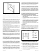


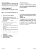
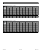
Table Of Contents

507330-01BPage 26 of 33 Issue 1809
5. Gas is ignited, ame sensor proves the ame, and the
combustion process continues.
6. If ame is not detected after rst ignition trial, the
ignition control will repeat steps 3 and 4 four more
times before locking out the gas valve. The ignition
control will then automatically repeat steps 1 through
6 after 60 minutes.
7. To interrupt the 60 minute, move thermostat from
“Heat” to “OFF” then back to “Heat”. Heating sequence
then restarts at step 1.
Gas Pressure Adjustment
Gas Flow (Approximate)
Gas Meter Clocking Chart
Capacity
Seconds for One Revolution
Natural LP
1 cu ft
Dial
2 cu ft
Dial
1 cu ft
Dial
2 cu ft
Dial
-070 55 110 136 272
-090 41 82 102 204
-110 33 66 82 164
Natural - 1000 btu/cu ft LP - 2500 btu/cu ft
Table 9.
Furnace should operate at least 5 minutes before checking
gas ow. Determine time in seconds for two revolutions of
gas through the meter. (Two revolutions assures a more
accurate time.) Divide by two and compare to time in
Table 9. If manifold pressure matches Table 10 and rate is
incorrect, check gas orices for proper size and restriction.
Remove temporary gas meter if installed.
NOTE: To obtain accurate reading, shut off all other gas
appliances connected to meter.
Supply Pressure Measurement
A threaded plug on the inlet side of the gas valve provides
access to the supply pressure tap. Remove the threaded
plug, install a eld provided barbed tting and connect a
manometer to measure supply pressure. See Table 10
for proper line pressure. Replace the threaded plug after
measurements have been taken.
Manifold Pressure Measurement
1. Remove the threaded plug from the outlet side of
the gas valve and install a eld provided barbed
tting. Connect to a manometer to measure manifold
pressure.
2. Start unit and allow 5 minutes for unit to reach steady
state.
3. While waiting for the unit to stabilize, observe the
ame. Flame should be stable and should not lift from
burner. Natural gas should burn blue.
4. After allowing unit to stabilize for 5 minutes, record
manifold pressure and compare to value given in
Table 10.
NOTE: Shut unit off and remove manometer as soon as an
accurate reading has been obtained. Take care to remove
barbed tting and replace threaded plug.
Manifold Pressure
Between 2000 and 7500 ft, certain units require manifold
pressure adjustments specied in Table 10. Manifold
pressure should be measured, and adjusted as required
during unit start up.
NOTE: LP/Propane installations require a gas conversion
Orice Kit as specied in Table 12.
Manifold Pressure and Line Pressure at Various Altitudes
Capacity
Manifold Pressure (in. w.c.)
1
Line Pressure (in. w.c.)
0 - 2000 ft. 2001 - 4500 ft. 4501 - 7500 ft. 7501 - 10000 ft. Minimum Max.
Nat.
Gas
LP
Gas
2
Nat.
Gas
LP
Gas
2
Nat.
Gas
LP
Gas
2
Nat.
Gas
3
LP
Gas
2
Nat.
Gas
LP
Gas
2
Nat. &
LP
070
3.5 10.0
3.2 10.0 2.8 10.0
3.5 10.0 4.5 11.0 13.0090 3.2 10.0 2.7 9.6
110 3.5 10.0 3.0 9.6
1
Manifold pressure adjustments based on 1020 Btu/ft3 gas for natural and 2500 Btu/ft
3
gas for LP (corrected to standard conditions).
Consult local utility for actual local heating value.
2
A natural to LP/Propane gas conversion Orice Kit is required to convert this unit. Refer to kit instructions for conversion procedure.
3
A high altitude natural Orice Kit is required.
Table 10.