
BG801UH Installation Manual

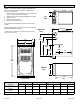

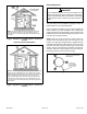
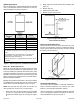
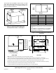
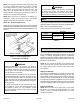
Table Of Contents

507330-01BPage 10 of 33 Issue 1809
NOTE: Heavy gauge perforated sheet metal straps may
be used to suspend the unit from roof rafters or ceiling
joists. When straps are used to suspend the unit in this
way, support must be provided for both the ends. The
straps must not interfere with the plenum or exhaust
piping installation. Cooling coils and supply and return air
plenums must be supported separately.
NOTE: When the furnace is installed on a platform in a
crawlspace, it must be elevated enough to avoid water
damage and to allow the evaporator coil to drain.
Return Air - Horizontal Applications
Return air must be brought in through the end of a furnace
installed in a horizontal application. The furnace is equipped
with a removable bottom panel to facilitate installation. See
Figure 9.
Figure 13. Horizontal Application
Unit Installed on Platform
Improper installation of the furnace can result in
personal injury or death. Combustion and ue products
must never be allowed to enter the return air system or
the living space. Use screws and joint tape to seal the
return air system to the furnace.
In platform installations with bottom return air, the furnace
should be sealed airtight to the return air plenum. A door
must never be used as a portion of the return air duct
system. The base must provide a stable support and an
airtight seal to the furnace. Allow absolutely no sagging,
cracks, gaps, etc..
The return and supply air duct systems must never
be connected to or from other heating devices such
as a replace or stove, etc.. Fire, explosion, carbon
monoxide poisoning, personal injury and/or property
damage could result.
WARNING
The inner blower panel must be securely in place when
the blower and burners are operating. Gas fumes,
which could contain carbon monoxide, can be drawn
into living space resulting in personal injury or death.
WARNING
Filters
This unit is not equipped with a lter or rack. A eld provided
high velocity lter is required for the unit to operate properly.
Table 1 lists recommended lter sizes.
A lter must be in place any time the unit is operating.
Furnace Cabinet
Width
Filter Size
Side Return Bottom Return
B - 17-1/2”
16 x 25 x 1
16 x 25 x 1
C - 21” 20 x 25 x 1
Table 1.
Duct System
Use industry approved standards (such as those published
by Air Conditioning Contractors of America or American
Society of Heating, Refrigerating and Air Conditioning
Engineers) to size and install the supply and return air duct
system. This will result in a quiet and low static system that
has uniform air distribution.
NOTE: Do not operate the furnace in the heating mode
with an external static pressure that exceeds 0.8 inches
w.c. Higher external static pressures may cause erratic
limit operation.
Supply Air Plenum
If the furnace is installed without a cooling coil, a removable
access panel must be installed in the supply air duct. The
access panel should be large enough to permit inspection
(either by smoke or reected light) of the heat exchanger
for leaks after the furnace is installed. The furnace access
panel must always be in place when the furnace is operating
and it must not allow leaks into the supply air duct system.
Return Air Plenum
NOTE: Return air must not be drawn from a room where
this furnace, or any other gas fueled appliance (i.e., water
heater), or carbon monoxide producing device (i.e., wood
replace) is installed.