
BG801UH Installation Manual

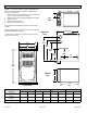
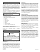
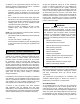

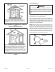
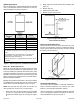
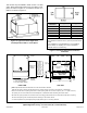
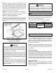
Table Of Contents

507330-01B Issue 1809 Page 7 of 33
Figure 4. Equipment in Conned Space - All Air from
Outside
(All Air through Ventilated Attic)
NOTE: The inlet and outlet air openings shall each have a free
area of at least one square inch per 4,000 Btu (645 mm² per
1.17 kW) per hour of the total input rating of all equipment in the
enclosure.
Figure 5. Equipment in Conned Space - All Air from
Outside
NOTE: Each air duct opening shall have a free area of at least one
square inch per 2,000 Btu (645 mm² per .59 kW) per hour of the
total input rating of all equipment in the enclosure. If the equipment
room is located against an outside wall and the air openings
communicate directly with the outdoors, each opening shall have
a free area of at least 1 square inch per 4,000 Btu (645 mm² per
1.17 kW) per hour of the total input rating of all other equipment in
the enclosure.
Setting Equipment
Do not install the furnace on its front or its back. Do not
connect the return air ducts to the back of the furnace.
Doing so will adversely affect the operation of the safety
control devices, which could result in personal injury or
death.
WARNING
The gas furnace can be installed as shipped in either the
upow position or the horizontal position.
Select a location that allows for the required clearances
that are listed on the unit nameplate. Also consider gas
supply connections, electrical supply, vent connection, and
installation and service clearances [24 inches (610 mm) at
unit front]. The unit must be level.
NOTE: Units with 1/2 hp and 3/4 hp blower motors are
equipped with three exible legs and one rigid leg. See
Figure 6. The rigid leg is equipped with a shipping bolt and
a at white plastic washer (rather than the rubber mounting
grommet used with a exible mounting leg). The bolt and
washer must be removed before the furnace is placed into
operation. After the bolt and washer have been removed,
the rigid leg will not touch the blower housing.
Figure 6.
Units with 1/2 HP & 3/4 HP
Blower Motor.