
BG801UH Installation Manual
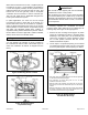
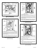
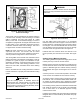
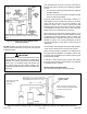
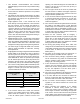
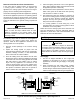
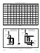
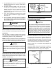
Table Of Contents

507330-01B Issue 1809 Page 11 of 33
When return air is drawn from a room, a negative pressure
is created in the room. If a gas appliance is operating in
a room with negative pressure, the ue products can be
pulled back down the vent pipe and into the room. This
reverse ow of the ue gas may result in incomplete
combustion and the formation of carbon monoxide gas.
This toxic gas might then be distributed throughout the
house by the furnace duct system.
In upow applications, the return air can be brought
in through the bottom or either side of the furnace. If a
furnace with bottom return air is installed on a platform,
make an airtight seal between the bottom of the furnace
and the platform to ensure that the unit operates properly
and safely. Use berglass sealing strips, caulking, or
equivalent sealing method between the plenum and the
furnace cabinet to ensure a tight seal. If a lter is installed,
size the return air duct to t the lter frame.
Venting
A 4 inch diameter ue transition is factory installed on
the combustion air inducer outlet of all models. Figure 15
shows the combustion air inducer as shipped from the
factory.
Figure 14. Mounting Screws Location
Figure 15. Upow Position
Top Vent Discharge
The unit will not vent properly with the ue transition
pointed down in the 6 o’clock position.
The combustion air inducer may be rotated clockwise
or counterclockwise by 90° to allow for top or side vent
discharge in all applications. When the unit is installed,
the ue transition must be in the 9 o’clock, 12 o’clock or
3 o’clock position.
IMPORTANT
If necessary reposition the combustion air inducer,
pressure switch and/or make-up box as needed per the
following steps. See Figure 15 through Figure 21.
1. Remove the four mounting screws (Figure 14) which
secure the combustion air inducer / pressure switch
assembly to the orice plate. Lift the assembly and
rotate it 90° clockwise or counter clockwise to either
the 3 o’clock position. Resecure with four screws.
Gasket should be left in place.
2. Use tin snips to cut preferred opening on the cabinet
for repositioning the ue outlet. Use the cut-out piece
as a cover plate to patch unused opening on cabinet.
• Gas supply piping must be brought into the unit from the right side
in order to accommodate the ue pipe.
• Cut combustion air inducer tubing from 9” to 8” to avoid
interference with inducer motor.
• Remove make-up box assembly (2 screws) and cut wire tie to
free make-up box wires. Re install make-up box on other side of
cabinet.
• Resecure make-up box wires: Either pull excess wires through
the blower compartment and secure using supplied wire tie, or
coil excess wire and secure to the gas manifold.
Figure 16. Upow Position
Left Side Vent Discharge