
BG801UH Installation Manual
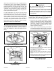
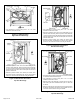
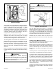
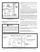
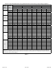
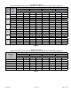
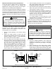
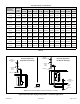
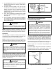
Table Of Contents

507330-01B Issue 1809 Page 13 of 33
Figure 21. Horizontal Right Position
Side Vent Discharge
These series units are classied as fan assisted Category
I furnaces when vertically vented according to the latest
edition of National Fuel Gas Code (NFPA 54 / ANSI
Z223.1) in the USA. A fan assisted Category I furnace is
an appliance equipped with an integral mechanical means
to either draw or force combustion products through the
combustion chamber and/or heat exchanger. This unit is
not approved for use with horizontal venting.
NOTE: Use these instructions as a guide. They do not
supersede local codes. This furnace must be vented
according to all local codes these installation instructions,
and the provided venting tables in these instructions.
The venting tables in this manual were extracted from the
National Fuel Gas Code (NFPA 54 / ANSI Z223.1) and are
provided as a guide for proper vent installation. Proper
application, termination, construction and location of vents
must conform to local codes having jurisdiction. In the
absence of local codes, the NFGC serves as the dening
document.
Refer to the tables and the venting information contained
in these instructions to properly size and install the venting
system.
Once the venting system is installed, attach the
“Disconnected Vent” warning sticker to a visible area
of the plenum near the vent pipe. See Figure 22. The
warning sticker is provided in the bag assembly. Order
kit 66W04 for additional stickers.
IMPORTANT
Asphyxiation hazard. The exhaust vent for this furnace
must be securely connected to the furnace ue transition
at all times.
WARNING
Figure 22. Vent Connection
Use self drilling sheet metal screws or a mechanical
fastener to rmly secure the vent pipe to the round collar of
the ue transition. If self drilling screws are used to attach
the vent pipe, it is recommended that three be used. Drive
one self drilling screw through the front and one through
each side of the vent pipe and collar. See Figure 22.
Install the rst vent connector elbow at a minimum of six
inches (152 mm) from the furnace vent outlet. See Figure
22.
Venting Using a Masonry Chimney
The following additional requirements apply when a lined
masonry chimney is used to vent this furnace.
Masonry chimneys used to vent Category I central furnaces
must be either tile lined or lined with a listed metal lining
system or dedicated gas vent. Unlined masonry chimneys
are prohibited. See Figure 23 and Figure 24 for common
venting.
A chimney with one or more sides exposed to the outside
of the structure is considered to be an exterior chimney.
An exterior masonry chimney that is not tile lined must be
lined with B1 vent or a listed insulated exible metal vent.
An exterior tile lined chimney that is sealed and capped
may be lined with a listed uninsulated exible metal vent.
If the existing chimney will not accommodate a listed metal
liner, either the chimney must be rebuilt to accommodate
one of these liners or an alternate approved venting
method must be found.
Insulation for the exible vent pipe must be an encapsulated
berglass sleeve recommended by the exible vent pipe
manufacturer.