
BG801UH Installation Manual
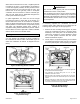
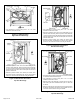
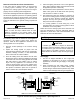
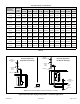
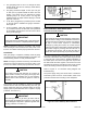
Table Of Contents

507330-01BPage 20 of 33 Issue 1809
3. The gas piping must not run in or through air ducts,
clothes chutes, gas vents or chimneys, dumb waiters,
or elevator shafts.
4. The piping should be sloped 1/4 inch (6.4 mm) per
15 feet (4.57 m) upward toward the meter from the
furnace. The piping must be supported at proper
intervals [every 8 to 10 feet (2.44 to 3.01 m)] with
suitable hangers or straps. Install a drip leg in vertical
pipe runs to the unit.
5. A 1/8” N.P.T. plugged tap or pressure post is located
on the gas valve to facilitate test gauge connection.
See Figure 27.
6. In some localities, codes may require the installation
of a manual main shut off valve and union (furnished
by the installer) external to the unit. The union must be
of the ground joint type.
Compounds used on threaded joints of gas piping must
be resistant to the actions of liquied petroleum gases.
IMPORTANT
NOTE: If emergency shutoff is necessary, shut off the
main manual gas valve and disconnect main power to the
furnace. The installer should properly label these devices.
Leak Check
After gas piping is completed, carefully check all piping
connections (factory and eld installed) for gas leaks. Use
a leak detecting solution or other preferred means.
NOTE: If emergency shutoff is necessary, shut off the main
manual gas valve and disconnect the main power to the
furnace. The installer should properly label these devices.
Some soaps used for leak detection are corrosive to
certain metals. Carefully rinse piping thoroughly after
leak test has been completed. Do not use matches,
candles, ame or other sources of ignition to check for
gas leaks.
CAUTION
The furnace must be isolated by closing its individual
manual shut-off valve and disconnecting from the gas
supply system the during any pressure testing of the gas
supply system at pressures less than or equal to 1/2 psig
(3.48 kPa, 14 inches w.c.).
When testing pressure of gas lines, gas valve must be
disconnected and isolated. See Figure 27. Gas valves
can be damaged if subjected to pressures greater than
1/2 psig (3.48 kPa, 14 inches w.c.).
IMPORTANT
Figure 27.
Electrical
ELECTROSTATIC DISCHARGE (ESD)
Precautions and Procedures
Electrostatic discharge can affect electronic components.
Take precautions during furnace installation and service
to protect the furnace’s electronic controls. Precautions
will help to avoid control exposure to electrostatic
discharge by putting the furnace, the control and the
technician at the same electrostatic potential. Neutralize
electrostatic charge by touching hand and all tools on
an unpainted unit surface, such as the gas valve or
blower deck, before performing any service procedure.
CAUTION
The unit is equipped with a eld make-up box on the left
hand side of the cabinet. The make-up box may be moved
to the right side of the furnace to facilitate installation. If
the make-up box is moved to the right side, clip the wire
ties that bundle the wires together. The excess wire must
be pulled into the blower compartment. Secure the excess
wire to the existing harness to protect it from damage.
Refer to Figure 31 for schematic wiring diagram and
troubleshooting.
The power supply wiring must meet Class I restrictions.
Protected by either a fuse or circuit breaker, select circuit
protection and wire size according to unit nameplate.
Figure 28. Interior Make-Up Box Installation