
BG801UH Installation Manual
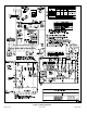
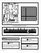
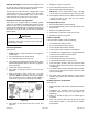

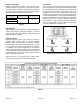
Table Of Contents

507330-01B Issue 1809 Page 21 of 33
Figure 29. Interior Make-Up Box Installation
NOTE: Unit nameplate states maximum current draw.
Maximum over current protection allowed is 15 AMP.
Holes are on both sides of the furnace cabinet to facilitate
wiring.
Install a separate (properly sized) disconnect switch near
the furnace so that power can be turned off for servicing.
Before connecting the thermostat, check to make sure the
wires will be long enough for servicing at a later date. Make
sure that thermostat wire is long enough to facilitate future
removal of blower for service.
Complete the wiring connections to the equipment. Use
the provided unit wiring diagram shown in Figure 31. Use
18 gauge wire or larger that is suitable for Class II rating for
thermostat connections.
Electrically ground the unit according to local codes or,
in the absence of local codes, according to the current
National Electric Code (ANSI/NFPA No. 70). A green
ground wire is provided in the eld make-up box.
NOTE: This furnace contains electronic components that
are polarity sensitive. Make sure that the furnace is wired
correctly and is properly grounded.
Accessory Terminals
One line voltage “ACC” 1/4” spade terminal is provided on
the furnace integrated control. See Figure 32 for integrated
control conguration. This terminal is energized when the
indoor blower is operating. Any accessory rated up to one
amp can be connected to this terminal with the neutral
leg of the circuit being connected to one of the provided
neutral terminals. If an accessory rated at greater than one
amp is connected to this terminal, it is necessary to use an
external relay.
One line voltage “HUM” 1/4” spade terminal is provided
on the furnace integrated control. See Figure 32 for
integrated control conguration. This terminal is energized
in the heating mode when the combustion air inducer is
operating. Any humidier rated up to one amp can be
connected to this terminal with the neutral leg of the circuit
being connected to one of the provided neutral terminals. If
a humidier rated at greater than one amp is connected to
this terminal, it is necessary to use an external relay.
One 24V “H” 1/4” spade terminal is provided on the furnace
control board. Any humidier rated up to 0.5 amp can be
connected to this terminal with the ground leg of the circuit
connected to ground or the “C” terminal. See Figure 32
for control board conguration. This terminal is energized
in the heating mode when the combustion air inducer is
operating.
Generator Use - Voltage Requirements
The following requirements must be kept in mind when
specifying a generator for use with this equipment:
• The furnace requires 120 volts ± 10% (Range: 108
volts to 132 volts).
• The furnace operates at 60 Hz ± 5% (Range: 57 Hz
to 63 Hz).
• The furnace integrated control requires both polarity
and proper ground. Both polarity and proper grounding
should be checked before attempting to operate the
furnace on either permanent or temporary power.
• Generator should have a wave form distortion of less
than 5% RHO.
Thermostat
Install the room thermostat according to the instructions
provided with the thermostat. See Figure 30 for thermostat
designations. If the furnace is being matched with a
heat pump, refer to the FM21 installation instruction or
appropriate dual fuel thermostat instructions.
Figure 30. Condensing Unit Thermostat Designations
(Refer to Specic Thermostat and Outdoor Unit)
* Note: “R” Required on some outdoor units.
Indoor Blower Speeds
1. When the thermostat is set to “FAN ON,” the indoor
blower will run continuously on the fan speed when
there is no cooling or heating demand.
2. When the unit is running in the heating mode, the
indoor blower will run on the heating speed.
3. When there is a cooling demand, the indoor blower will
run on the cooling speed.