
BG801UH Installation Manual
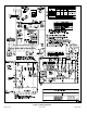
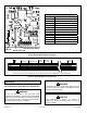

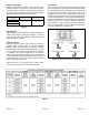
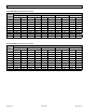
Table Of Contents
507330-01BPage 28 of 33 Issue 1809
Constant Torque Motor
These units are equipped with a constant torque ECM
motor. It has a DC motor coupled to an electronic control
module,both contained in the same motor housing. The
motor is programmed to provide constant torque at each of
the ve selectable speeds. The motor has ve speed taps.
Each tap requires 24 volts to energize.
Thermostat Heat Anticipation
Set the heat anticipator setting (if adjustable) according to
the amp draw listed on the wiring diagram that is attached
to the unit.
NOTE: Do not secure the electrical conduit directly to the
air ducts or structure.
Electrical
1. Check all wiring for loose connections.
2. Check for the correct voltage at the furnace (furnace
operating). Correct voltage is 120VAC ± 10%.
3. Check amp-draw on the blower motor with inner
blower panel in place.
Unit Nameplate__________ Actual_______________
Blower Speeds
Follow the steps below to change the blower speeds.
1. Turn off electrical power to furnace.
2. Remove blower access panel.
3. Disconnect existing speed tap at integrated control
speed terminal.
NOTE: Termination of any unused motor leads must
be insulated.
4. Place unused blower speed tap on integrated control
“PARK” terminal or insulate.
5. Refer to blower speed selection chart on unit wiring
diagram for desired heating or cooling speed. See
Blower performance data.
6. Connect selected speed tap at integrated control
speed terminal.
7. Resecure blower access panel.
8. Turn on electrical power to furnace.
9. Recheck temperature rise.
Other Unit Adjustments
Primary and Secondary Limits
The primary limit is located on the heating compartment
vestibule panel. The secondary limits (if equipped) are
located in the blower compartment, attached to the back
side of the blower. These auto reset limits are factory set
and require no adjustment.
Flame Rollout Switches
This manually reset switches are located on the Front of
the burner box.
Pressure Switch
The pressure switch is located in the heating compartment
adjacent to the combustion air inducer. The switch checks
for proper combustion air inducer operation before allowing
ignition trial. The switch is factory set and requires no
adjustment.
Temperature Rise
After the furnace has been started, and supply and return
air temperatures have been allowed to stabilize, check the
temperature rise. If necessary, adjust the blower speed to
maintain the temperature rise within the range shown on
the unit nameplate. Increase the blower speed to decrease
the temperature. Decrease the blower speed to increase
the temperature rise. Failure to adjust the temperature rise
may cause erratic limit operation.