
BG952-V Specifications Sheet

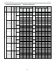


Table Of Contents

Page 2
95% GAS FURNACE
BG952
UPFLOW/HORIZONTAL
PHYSICAL AND ELECTRICAL DATA
Model
1st Stage
2nd Stage
AFUE
(ICUS)
Nom.
Cooling
Capacity
(tons)
Gas
Inlet
(in.)
Volts/
Hz/
Phase
Min.
Time
Delay
Breaker
or Fuse
Nominal
F.L.A.
Trans.
(V.A.)
Approx.
Weight
(lbs.)
Input
(Btuh)
Output
(Btuh)
Input
(Btuh)
Output
(Btuh)
BG952UH045BV12
29,000
28,000
44,000
42,00
0
95.0
3
1/2
120-60-
1
15
7.7
40
130
BG952UH070BV12
43,000
41,000
66,000
62,00
0
95.0
3
1/2
120-60-
1
15
7.7
40
138
BG952UH090CV12
57,000
55,000
88,000
84,00
0
95.0
3
1/2
120-60-
1
15
7.7
40
154
BG952UH090CV20
57,000
55,000
88,000
85,00
0
95.0
5
1/2
120-60-
1
20
12.8
40
166
BG952UH110CV20
72,000
70,000
110,000
105,0
00
95.0
4
1/2
120-60-
1
15 12.8
40
173
BG952UH135DV20
88,000
84,000
132,000
126,0
00
95.0
5
1/2
120-60-
1
20
12.8
40
188
Note: For vent length and clearances to combustibles, please reference installation instructions.
FILTER REQUIREMENT DATA
Airflow
Descriptor
Disposable Filters
Cleanable Filters
Minimum Area
(sq. in.)
Minimum Area
(sq.in.)
12
576
288
16
768
384
20
960
480
1.
The Airflow Descriptor is the two digits following the "B", "C", or "D" in the model number; e.g. "20" is the Airflow Descriptor.
2.
Areas shown for permanent filters are based on filters rated at 600 feet per minute face velocity.