Ceiling Cassette Indoor Air Handler Installation Manual Models: BM12MCC BM18MCC IMPORTANT NOTE: Read this manual carefully before installing or operating your new air conditioning unit. Make sure to save this manual for future reference. This manual only describes the outdoor unit of user’s. When using the indoor unit, refer to the user’s manual of indoor unit.
Table of Contents 1. Safety Precautions.......................................................................................................................................... 02 Warnings................................................................................................................................................................... 04 Cautions...................................................................................................................................................
Safety Precautions 1 Read Before Using Incorrect usage may cause serious damage or injury. The seriousness of potential damage or injuries is classified as either a WARNING or CAUTION. WARNING CAUTION This symbol indicates that ignoring instructions may cause death or serious injury. This symbol indicates that ignoring instructions may cause moderate injury to your person, or damage to your unit or other property. This symbol indicates that you must never perform the action indicated.
WARNING • Wiring routing must be properly arranged so that control board cover is fixed properly. If control board cover is not fixed perfectly, it can cause heat-up at connection point of terminal, fire or electrical shock. • If the supply cord is damaged, it must be replaced by the manufacture or its service agent or a similarly qualified person in order to avoid a hazard. • An electrical disconnect switch having a contact separation of at least 0.
Installation Summary 2 Installation Summary Installation information • To install properly, please read this "installation manual" at first. • The air conditioner must be installed by qualified persons. • When installing the indoor unit or its tubing, please follow this manual as strictly as possible. • If the air conditioner is installed on a metal part of the building, it must be electrically insulated according to the relevant standards to electrical appliances.
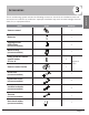
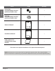
3 Accessories Name Shape Quantity Remote control 1 Batteries 2 Tapping screws (M3X10mm) (on some models) 2 Metal champ (on some models) 1 Fixing screw for remote control holder ST2.
Accessories Name Shape Quantity Drain plug (only heat pump models) (with the outdoor unit) 1 Seal ring (only heat pump models) (with the outdoor unit) 1 Owner’s Manual 1 Installation Manual 1 Paper pattern for installation (on some models) 1 This indoor unit requires installation of an optional decoration panel. NOTE: All the pictures in this manual are for explanation purpose only. There may be slightly different from the air conditioner you purchased ( depend on model ).
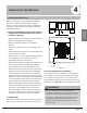
4 Indoor Unit Installation 39.4in 2 1 • Where nothing blocks air passage. 39.4in • Where optimum air distribution can be ensured. 39.4in 2 Indoor Unit Installation 1. Select an installation site where the following conditions are fulfilled and that meets your customer's approval. 98.4in 10.2in When the conditions in the ceiling are exceeding 86°F and a relative humidity of 80%, or when fresh air is inducted into the ceiling, an additional insulation is required (minimum 0.
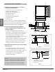
1 20.6in 1. Relation of ceiling opening to unit and suspension bolt position. Adjust the position to ensure the gaps between the indoor unit and the four sides of false ceiling are even. The indoor unit's lower part should sink into the false ceiling for 0.9in. See Fig. 4.3. 2. Create the ceiling opening needed for indoor installation where applicable. (For existing ceilings.) •C reate the ceiling opening required for installation.
Install the indoor unit When installing optional accessories, read also the installation manual of the optional accessories. Depending on the field conditions, it may be easier to install optional accessories before the indoor unit is installed (except for the decoration panel). However, for existing ceiling, install fresh air inlet component kit and branch duct before installing the unit. 1. Install the indoor unit. 2. Securing the hanger bracket see figure below.
5 Refrigerant Piping Installation WARNING All field piping must be provided by a licensed refrigeration technician and must comply with the relevant local and national codes Refrigerant Piping Installation CAUTION • DO NOT mix anything other than the specified refrigerant, such as air, etc., inside the refrigerant circuit. • Execute heat insulation work completely on both sides of the gas piping and liquid piping. Otherwise, this can sometimes result in water leakage.
5.1 Flaring the pipe end 5.2 Refrigerant Piping 1. Cut the pipe end with a pipe cutter. 2. Remove burrs with the cut surface facing downward so that the chips do not enter the pipe. See Fig 5.3. 1. Use Nylog or similar approved refrigerant sealant. Coat here with Nylog 3. Put the flare nut on the pipe. 4. Flare the pipe. Set exactly at the position shown in Fig 5.5. 5. Check that the flaring is properly made. Fig 5.6 Cut exactly at right angles Remove burrs A Outer diam. Spanner Max.
6 Connecting The Drain Pipe 6.1 Installation of drain piping Install the drain piping as shown in figure below and take measures against condensation. Use PVC pipe, use of plastic, flexible piping is discouraged. 3~5ft Hanging bar 1 1/100 gradient 2 3 4 1 - Drain socket (attached to the unit) 2 - Metal clamp 3 - Drain hose 4 - Insulation (field supply) Fig 6.1 6.3 How to perform piping • Keep pipe size equal to or greater than that of the discharge pipe of the unit.
CAUTION • Install the drain lift pipes no higher than 21". • Install the drain lift pipes at a right angle to the indoor unit and no more than 12" from the unit. • To prevent air bubbles, install the drain hose level. • The incline of drain hose should be no more than 3"so that the drain socket does not have to withstand additional force. • To ensure a downward slope of 1:100, support the drain line every 3'. • When unifying multiple drain pipes, install the pipes as shown in figure below.
7 Electrical Wiring CAUTION • All field wiring and components must be installed by a licensed electrician and must comply with relevant European and national regulations. • Use copper wire only. • Follow the 'Wiring diagram' attached to the unit body to wire the outdoor unit, indoor units and the remote controller. • A circuit breaker capable of shutting down power supply to the entire system must be installed.
8 Decorative Panel Installation Detach the intake grille After installing the decoration panel, ensure that there is no space between the unit body and decoration panel. Otherwise air may leak through the gap and cause dewdrop. See figure below. Slide the 2 grille hooks toward the middle of the decoration panel. 1 - Intake grille 1 2 - Grille hook 2 Fig 8.1 Open the intake grille and remove Fig 8.4 Mount the intake grille Ensure that the grille is properly seated in the groove of the panel.
Install Outdoor Unit (see separate manual) When you have finished installing all indoor air handlers, proceed to installation of the outdoor unit. Complete installation instructions and startup procedures are given in the outdoor unit installation manual. Copies are always available at AlpineHomeAir.com by searching your unit's model number and scrolling to Documents. The design and specifications are subject to change without prior notice for product improvement. AlpineHomeAir.