
Ceiling Cassette Air Handler Installation Manual


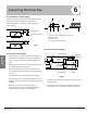


6.4 Test the drain piping
After the piping work is nished, check if drainage
ows smoothly.
When electric wiring work is nished, check
drainage ow during COOL running, explained in
"Test operation".
Fig 6.4 Fig 6.5
CAUTION
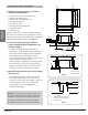
• Install the drain lift pipes no higher than 21".
• Install the drain lift pipes at a right angle to the indoor unit and no more than 12" from the unit.
• To prevent air bubbles, install the drain hose level.
• The incline of drain hose should be no more than 3"so that the drain socket does not have to
withstand additional force.
• To ensure a downward slope of 1:100, support the drain line every 3'.
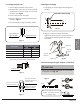
• When unifying multiple drain pipes, install the pipes as shown in gure below. Select
converging drain pipes whose gauge is suitable for the operating capacity of the unit.
• Do not connect the drain piping directly to sewage pipes that smell of ammonia. The
ammonia in the sewage might enter the indoor unit through the drain pipes and corrode the
heat exchanger.
0-530
100
T-Joint converging drain pipes
T-Joint converging drain pipes
Unit
: mm
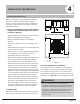
3.9in
Fresh air intake 2.6i
n
3in
2.6in
4.2in
4.2in
Water
receiver
Page 15
Revised 5/14/2020
Connecting
The Drain Pipe