
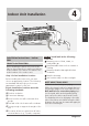
Single Zone Installation Manual

Page 14
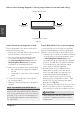
CAUTION
Be extremely careful not to dent or damage the piping while bending them away from the
unit. Any dents in the piping will affect the unit’s performance.
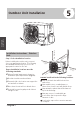
Step 4: Prepare refrigerant piping
The refrigerant piping is inside an insulating
sleeve attached to the back of the unit. You must
prepare the piping before passing it through the
hole in the wall. Refer to the Refrigerant Piping
Connection section of this manual for detailed
instructions on pipe flaring and flare torque
requirements, technique, etc.
1. Based on the position of the wall hole r
elative
to the mounting plate, choose the side f
r
om
which the piping will exit the unit.
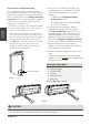
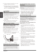
2. If the wall hole is behind the unit, keep the
knock-out panel in place. If the wall hole is to
the side of the indoor unit,
r
emove the plastic
knock-out panel from that side of the unit.
(See
Fig. 3.3 ). This will create a slot thr
ough
which your piping can exit the unit. Use
needle nose pliers if the plastic panel is too
di
fficult to remove by hand.
3. Use scissors to cut down the length of the
insulating sleeve to reveal about 15cm (6in)
of the refrigerant piping. This serves two
purposes:
• To facilitate the Refrigerant Piping
Connection process
• To facilitate Gas Leak Checks and enable
you to check for dents
4.
If existing connective piping is alr
eady
embedded in the wall, proceed directly to
the Connect Drain Hose step. If there is no
embedded piping, connect the indoor unit’s
refrigerant piping to the connective piping
that will join the indoor and outdoor units.
Refer to the Refrigerant Piping Connection
section
of this manual for detailed instructions.
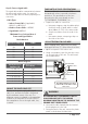
5.
Based on the position of the wall hole
relative to the mounting plate, determine the
necessary angle of your piping.
6.
Grip the r
efrigerant piping at the base of the
bend.
7.
Slowly, with even p
ressure, bend the piping
towards the hole. Do not dent or damage the
piping during the process.
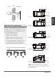
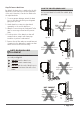
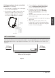
NOTE ON PIPING ANGLE
Refrigerant piping can exit the indoor unit from
four different angles:
•
Left-hand side
•
Left rear
•
Right-hand side
•
Right rear
Refer to
Fig. 3.4 for details.
Fig. 3.3
Fig. 3.4
Indoor Unit
Installation
Knock-out Panel