Multi Zone Outdoor Installation Manual IMPORTANT NOTE: • Read this manual carefully before installing or operating your new air conditioning unit. Make sure to save this manual for future reference. • This manual only describes the installation of outdoor unit. When installing the indoor unit, refer to the installation manual of indoor unit.
Table of Contents Installation Manual 1 Safety Precautions..................................04 2 Accessories...................................................05 3 Installation Overview............................06 4 Specifications .............................................07 5 Outdoor Unit Installation............................
6 Refrigerant Piping Connection.......................... 11 L N 7 Wiring................................................... 14 Wiring Diagrams............................... 16 8 Refrigerant Handling...................................... 19 Procedure..................................................................19 Refrigerant chart....................................................21 Adding refrigerant.................................................21 9 Test Run...............................
1 Safety Precautions Read Safety Precautions Before Installation Incorrect installation due to ignoring instructions can cause serious damage or injury. The seriousness of potential damage or injuries is classified as either a WARNING or CAUTION. WARNING Failure to observe a warning may result in death. The appliance must be installed in accordance with national regulations. Failure to observe a caution may result in injury or equipment damage.
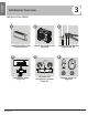
2 Accessories The air conditioning system comes with the following accessories. Use all of the installation parts and accessories to install the air conditioner. Improper installation may result in water leakage, electrical shock and fire, or equipment failure. Name Shape Quantity Installation plate 1 Plastic expansion sheath 5-8 (depending on models) Self-Tapping Screw A ST 3.
Installation Overview 3 Installation Overview INSTALLATION ORDER 1 Install the indoor unit (separate manual) 4 L 2 3 Install the outdoor unit (Page 09) Connect the refrigerant pipes (Page 12) 5 6 N MC Connect the wires (Page 14) Page 6 MC Evacuate the refrigeration system (Page 21) Perform a test run (Page 24) Revised 5/14/2020
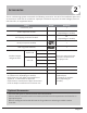
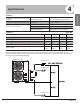
4 Specifications Number of units that can be used together Connected units 1-5 units depending on model Compressor stop/start frequency Stop time 3 min or more voltage fluctuation within ±10% of rated voltage voltage drop during start within ±15% of rated voltage interval unbalance within ±3% of rated voltage Power source voltage Table 5.2 Unit: feet. 2 Zone 3 Zone 4 Zone 5 Zone Max. length for all rooms 131’ 197’ 262’ 262’ Max.
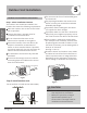
5 Outdoor Unit Installation Outdoor Unit Installation Instructions Step 1: Select installation location. Outdoor Unit Installation The outdoor unit should be installed in the location that meets the following requirements: lace the outdoor unit as close to the indoor P unit as possible. nsure that there is enough room for E installation and maintenance. The air inlet and outlet must not be obstructed or exposed to strong wind.
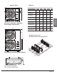
Outdoor Units Table 6.1: Model H D H A B BM18M23C 33.27" 14.29" 27.64" 21.3" 13.8" BM27M23C 37.2" 16.5" 31.9" 26.5" 15.9" BM36M23C 37.2" 16.5" 31.9" 26.5" 15.9" BM48M22C 37.5" 16.3" 52.5" 25" 15.9" BMHH18M22C 37.2" 16.5" 31.9" 26.5" 15.9" BMHH27M22C 37.2" 16.5" 31.9" 26.5" 15.9" BMHH36M22C 37.5" 16.3" 52.5" 25" 15.9" BMHH48M22C 37.5" 16.3" 52.5" 25" 15.
above NOTE: Be sure to maintain minimum clearances for optimum operation as shown below. om ” fr ” on ck ba ll wa left 2. Using a 2.5” hole bit, drill a hole in the wall. ” on right Outdoor Unit Installation P ” in nt fro You must drill a hole in the wall for the refrigerant piping, and the signal cable that will connect the indoor and outdoor units. 1. Determine the location of the wall hole based on the location of the outdoor unit.
6 Refrigerant Piping Connection Safety Precautions WARNING All field piping must be completed by a licensed technician and must comply with the local and national regulations. • When the air conditioner is installed in a small room, measures must be taken to prevent the refrigerant concentration in the room from exceeding the safety limit in the event of refrigerant leakage. If the refrigerant leaks and its concentration exceeds its proper limit, hazards due to lack of oxygen may result.
Pipe Reamer Pipe gauge Point down Flaring torque Flare dimension (A) (Unit: Inch) Min. 14 ft/ lbs 0.33 0.34 3/8" 18 ft/ lbs 0.52 0.53 Step 3: Flare pipe ends. 1/2" 26 ft/ lbs 0.64 0.65 Proper flaring is essential to achieve an airtight seal. 5/8" 34 ft/ lbs 0.76 0.78 1. After removing burrs from cut pipe, seal the ends with PVC tape to prevent foreign materials from entering the pipe. 2. Sheath the pipe with insulating material. 3. Place flare nuts on both ends of pipe.
Torque Requirements Outer Diameter of Pipe (inch) Tightening Torque (ft/lb) Add. Tightening Torque (ft/lb) 1/4" 11 ft/ lb 11.8 ft/ lb 3/8" 18.4 ft/ lb 19.18 ft/ lb 1/2" 25.8 ft/ lb 26.55 ft/ lb 5/8" 33.19 ft/ lb 34.67 ft/ lb NOTE: Use both a spanner and a torque wrench when connecting or disconnecting pipes to/from the unit. NOTE ON MINIMUM BEND RADIUS Bend the pipe with thumb Refrigerant Piping Connection Carefully bend the tubing in the middle according to the diagram below.
7 Wiring Safety Precautions Wiring WARNING • Be sure to disconnect the power supply before working on the unit. • All electrical wiring must be done according to local and national regulations. • Electrical wiring must be done by a qualified technician. Improper connections may cause electrical malfunction, injury and fire. • An independent circuit and single outlet must be used for this unit. DO NOT plug another appliance or charger into the same outlet.
Follow these instructions to prevent distortion when the compressor starts: • The unit must be connected to the main outlet. Normally, the power supply must have a low output impedance of 32 ohms. • No other equipment should be connected to the same power circuit. • The unit’s power information can be found on the rating sticker on the product. 2. Remove the electric cover of the outdoor unit.
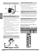
Wiring Diagrams CAUTION Connect the connective cables to the terminals, as identified, with their matching numbers on the terminal block of the indoor and outdoor units. For example, in the US models shown in the following diagram, Terminal 1(A) of the outdoor unit must connect with terminal 1 on the indoor unit.
BM27M three zone condenser 1 (B) 2 (B) L1 1 (B) 2 (B) L1 3 (B) L2 1 (C) 1 (A) 2 (C) 2 (A) 3 (B) 1 (C) L2 2 (C) 1 (A) 3 (C) 2 (A) 3 (A) 3 (C) 3 (A) 1 (B) 2 (B) L1 Ground 3 (B) 1 (C) L2 2 (C) 1 (A) 3 (C) 2 (A) 3 (A) POWER 1 2 3 1 2 3 TO A 1 2 3 TO B TO C BM36M four zone condenser L1 1 (B) L1 2 (B) L2 3 (B) 1 (C) 1 (A) 2 (C) 2 (A) 3 (C) 1 (D) 2 (D) 3 (B) L2 1 (C) 2 (C) 1 (A) 2 (A) 3 (C) 1 (D) 2 (D) 3 (D) 3 (A) 3 (D) 3 (A) 1 (B) 2 (B) L1 Gr
BM48M five zone condenser L1 1 (A) L2 2 (C) 3 (C) 3 (A) 1 (D) 1 (B) 2 (D) 2 (B) 3 (D) 3 (B) 1 (E) 2 (E) 3 (E) Wiring 1 (C) 2 (A) Ground Page 18 POWER 1 2 3 1 2 3 1 2 3 1 2 3 1 2 3 TO A TO B TO C TO D TO E Revised 5/14/2020
CAUTION After confirmation of the above conditions, follow these guidelines when performing wiring: • Always have an individual power circuit specifically for the air conditioner. • Always follow the circuit diagram posted on the inside of the control cover. • Screws fastening the wiring in the casing of electrical fittings may come loose during transportation. Because loose screws may cause wire burn-out, check that the screws are tightly fastened. • Check the specifications for the power source.
8 Refrigerant handling: Leak Test, Evacuation, and Refrigerant Charging Tools needed: • • • • • • Dry nitrogen tank and regulator R410a manifold gauge set 1/4" to 5/16" mini-split gauge adapter (yellowjacket) Soap bubble solution sprayer Micron gauge Vacuum pump Manifold Gauge Compound gauge Pressure gauge -76cmHg High pressure valve Low pressure valve Charge hose Charge hose Vacuum pump Low pressure valve Procedure: 1. Open King valves (see Fig. 9.
8. Test Vacuum Let lineset sit in vacuum and watch for rise in the gauge over 15 - 30 minutes. A slow rise is normal. If the gauge stays below 500, proceed to next step. If a leak is suspected, repeat Step 8. If moisture is suspected, breaking vacuum with dry nitrogen to 5 psi may help remove the moisture. Once vacuum test is complete, follow the next step to release refrigerant into Zone A. 9. Release refrigerant (See Fig. 9.
Table 9.1 Refrigerant Chart Directions: 1. Find your condenser model below. 2. Enter lineset length for each connected zone - calculate total. 3. Subtract your unit's pre-charge from the total. 4. If the result is negative, system is fully charged, do nothing. 5. If result is positive. multiply by 0.16. 6 This is how much to add.
9 Test Run Before Test Run Test Run Instructions A test run must be performed after the entire system has been completely installed. Confirm the following points before performing the test: 1. Open both the liquid and gas stop valves. a) The indoor and outdoor units are properly installed. 3. Set the air conditioner to COOL mode. b) P iping and wiring are properly connected. c) No obstacles near the inlet and outlet of the unit that might cause poor performance or product malfunction.
Function of Automatic Wiring/Piping Correction 10 Automatic Wiring/Piping Correction Function More recent models now feature automatic correction of wiring/piping errors. Press the "check switch" on the outdoor unit PCB board for 5 seconds until the LED displays "CE”, indicatomg that this function is working, Approximately 5-10 minutes after the switch is pressed, the "CE" disappears, meaning that the wiring/piping error is corrected and all wiring/piping is properly connected.
The design and specifications are subject to change without prior notice for product improvement. AlpineHomeAir.